You can eliminate layer gaps by calibrating your Z-axis steps per millimeter settings, which control vertical movement accuracy in your 3D printer. Start by printing a test cube and measuring its actual height with calipers, then compare this to your commanded height. Calculate the correct steps/mm value using your motor specifications and lead screw pitch, then update your firmware settings accordingly. Proper calibration guarantees consistent layer heights and eliminates those frustrating horizontal gaps that compromise your print quality.
Understanding Z-Axis Steps Per Millimeter Settings
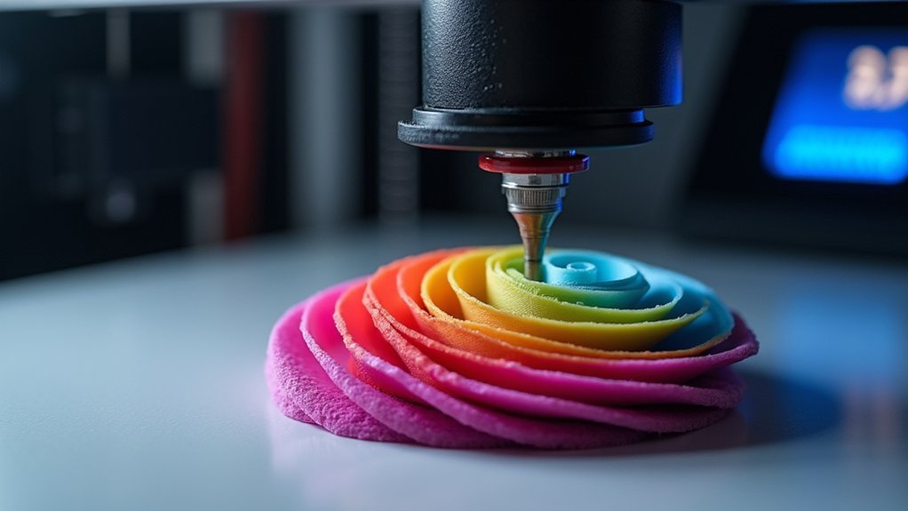
When you’re fine-tuning your 3D printer’s performance, the Z-axis steps per millimeter setting stands as one of the most critical parameters you’ll need to master.
This Steps/mm value determines how far your Z-axis moves vertically for each step signal sent to the stepper motor, directly controlling layer height precision during calibration.
Most printers use approximately 400 Steps/mm, though your specific lead screw and motor configuration may require adjustments.
When misconfigured, you’ll notice layer gaps that compromise material deposition and create inconsistent layers.
Proper Z-axis calibration guarantees accurate vertical movement, eliminating adhesion problems and maintaining uniform layer heights.
Getting this setting right is vital for quality prints, as even small deviations can cause significant dimensional inaccuracies and structural weaknesses in your finished parts.
Identifying Layer Gap Symptoms and Root Causes
You’ll notice layer gaps through distinct visual patterns like horizontal lines, ridges, or visible separations between layers that create an uneven surface finish.
These gaps often appear as consistent spacing issues that compromise your print’s structural integrity and aesthetic quality.
Flow rate problems frequently cause these symptoms, as inconsistent material deposition creates irregular layer bonding that manifests as visible defects in your final print.
Visual Gap Patterns
Although your 3D printer might seem perfectly calibrated, visual gap patterns often reveal hidden Z-axis issues that aren’t immediately obvious during setup. These discrepancies manifest as inconsistent line widths or missing sections, particularly in your first few layers where misalignment becomes most apparent.
| Gap Pattern | Likely Cause | Solution |
|---|---|---|
| Zigzagging gaps | Infill patterns issues | Adjust retraction settings |
| Horizontal lines | Layer height problems | Recalibrate Z-axis steps |
| Random voids | Multiple factors | Check all calibration |
You’ll notice these visual gap patterns become more pronounced in larger prints, where slight Z-axis deviations accumulate into significant defects. Monitor your retraction distance and layer height settings closely, as proper calibration of these parameters directly impacts your print quality and eliminates troublesome layer gaps.
Flow Rate Issues
While visual gap patterns provide initial clues about Z-axis problems, flow rate issues create their own distinct symptoms that you can identify through careful observation of your print’s layer consistency.
When your Z offset is properly calibrated but layer gaps persist, inadequate flow rate becomes the likely culprit. You’ll notice insufficient material deposition, particularly in first layers, creating visible gaps between extrusion lines.
Different nozzle sizes and filament types require specific flow rate adjustments to achieve ideal extrusion rates. Start with 5% incremental changes while monitoring print quality improvements.
Conduct flow tower tests to visually assess how adjustments affect layer adhesion. Look for uneven layer heights and inconsistent material melting as key indicators.
Fine-tune using advanced slicer settings, especially when printing with larger nozzles or high-speed configurations.
Measuring Actual Vs Expected Z-Axis Movement
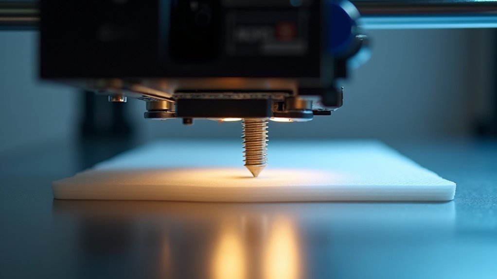
Accurate Z-axis calibration starts with measuring how far your printhead actually moves compared to what your firmware expects.
You’ll need to print a test object with known dimensions, like a 10mm cube, then measure its height with calipers.
Calculate your actual movement by dividing the measured height by the Z-axis steps commanded in your G-code.
Divide your measured cube height by the commanded Z-steps to determine your printer’s actual movement accuracy.
Compare this against your firmware’s current steps/mm setting to identify discrepancies.
If your printed object measures differently than expected, you’ll need to adjust the steps/mm value in your firmware’s motion settings.
This calibration process directly impacts print quality by ensuring each layer height matches your slicer’s specifications, eliminating gaps and inconsistencies.
Calculating Correct Steps Per Millimeter Values
Once you’ve measured your Z-axis movement, you’ll need to calculate the correct steps per millimeter value using your stepper motor specifications and lead screw pitch.
The standard formula divides your motor’s steps per revolution by the lead screw’s pitch, but you’ll want to test this calculated value against real-world performance.
Fine-tuning through test prints guarantees your layers match the expected height and eliminates gaps or compression issues.
Measuring Actual Movement Distance
Before you can calculate the correct steps per millimeter value, you’ll need to physically measure how far your Z-axis actually moves when commanded to travel a specific distance. Start by positioning your nozzle at a known reference point, then command a 10mm upward movement through your printer’s control interface.
Use precise calipers or a ruler to measure the actual distance traveled. This measuring process is vital for accurate Z-axis steps calibration, as it reveals discrepancies between commanded and actual movement.
| Test Run | Commanded Distance | Actual Distance Measured |
|---|---|---|
| 1 | 10.0 mm | 9.8 mm |
| 2 | 10.0 mm | 9.7 mm |
| 3 | 10.0 mm | 9.9 mm |
Record multiple measurements to guarantee consistency. Inaccurate movement directly causes layer gaps in your prints, making this calibration essential for quality results.
Formula for Steps Calculation
After gathering your measurement data, you’ll need to calculate the correct steps per millimeter value using a specific formula.
The equation is: Steps per mm = (Motor Steps per Revolution × Microstepping) / (Lead Screw Pitch × 1000).
For instance, with 200 motor steps per revolution, 16x microstepping, and 2mm lead screw pitch, you’d get (200 × 16) / (2 × 1000) = 1.6 steps per mm.
Once calculated, update your firmware settings in Marlin with this new Z-axis value.
Verify accuracy by printing a calibration cube or test print to check layer gaps and overall height precision.
Fine-tune the steps per mm if your test results show dimensional inaccuracies.
Testing and Fine-Tuning
Test your calculated steps per millimeter value by commanding your printer to move the Z-axis a precise distance, then measure the actual movement with calipers or a ruler. If there’s discrepancy between commanded and actual movement, recalculate using the corrected measurement.
Update your firmware settings with the new Z-axis steps per millimeter value, considering your specific gear ratio and lead screw pitch combination.
After calibration, run a test print like a single-layer square to evaluate layer adhesion and consistency. You’ll notice improved first-layer quality and eliminated gaps between subsequent layers.
Fine-tuning may require multiple iterations—make small adjustments and test again until you achieve perfect layer adhesion. This measurement-based approach guarantees your Z-axis moves exactly as programmed, resulting in consistent layer heights and superior print quality throughout your projects.
Implementing Z-Axis Calibration Through Firmware Updates
When your 3D printer’s Z-axis movements don’t match the intended layer heights, firmware updates provide the most effective solution for achieving precise calibration.
Modern Marlin firmware includes enhanced Z-axis step calibration features that dramatically improve print accuracy and eliminate frustrating layer gaps.
You’ll need to adjust your steps per millimeter value through G-code commands or your printer’s LCD interface. This modification guarantees your Z-axis movements correspond exactly to intended layer heights, preventing under-extrusion and improving layer adhesion.
Regular firmware updates introduce new calibration features and essential bug fixes that directly impact Z-axis performance.
Testing Print Quality After Z-Axis Adjustment
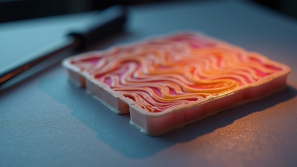
Three essential test prints will reveal whether your Z-axis calibration adjustments have successfully resolved layer gap issues and improved overall print quality.
Start with a calibration cube to evaluate layer adhesion and surface quality improvements. Monitor your first layer closely during printing—proper nozzle height guarantees even extrusion and eliminates gaps between layers.
Use a micrometer to measure printed layer thickness, verifying your adjusted Z-axis settings produce consistent results.
Watch for signs of under-extrusion or over-extrusion, such as gaps or excessive material buildup, which indicate you’ll need further calibration adjustments.
Compare prints before and after your Z-axis calibration to see clear evidence of improvements. A successful test print will show enhanced layer adhesion, smooth surface quality, and consistent extrusion throughout the entire print.
Frequently Asked Questions
What Is Z-Axis Controller Calibration?
You’ll adjust your printer’s firmware to guarantee the Z-axis motor moves the exact distance commanded. This calibration process typically involves measuring actual movement against expected movement to determine correct steps per millimeter settings.
What Is Z-Offset Calibration?
You’ll adjust your print nozzle’s vertical position relative to the bed surface through Z-offset calibration. This guarantees proper first layer adhesion by compensating for material thickness variations and bed surface differences.
How to Calibrate Z-Axis on Prusa?
Navigate to your Prusa’s LCD menu and select “Calibration,” then “Z-Axis Calibration.” Use paper between the nozzle and bed to gauge proper distance. Print a test cube afterward to verify your first layer quality.
How to Perfectly Calibrate Ender 3?
You’ll need to level your bed using paper to check nozzle distance, adjust Z-offset settings, print calibration patterns, clean lead screws regularly, and verify steps/mm settings match 400 for proper movement.


Leave a Reply