
You can maximize your 3D printing efficiency by using variable infill density techniques that strategically place high-density infill only in critical areas. Start by selecting advanced slicing software like PrusaSlicer that supports modifier objects for creating density zones. Set base layers to 30-100% density for stability, then gradually reduce to 10-20% in upper sections. Position 100% infill around mounting holes and stress points while using lighter patterns elsewhere. Test small models first to validate settings and monitor layer changes for weak points. The following thorough strategies will transform your printing approach.
Understanding Variable Infill Density Fundamentals
When you’re looking to optimize your 3D prints for both strength and material efficiency, variable infill density becomes an essential technique that lets you customize the internal structure of your parts.
This approach allows you to strategically place stronger infill density in critical areas while maintaining lighter printing infill elsewhere.
You’ll find variable infill particularly valuable when reinforcing sections around mounting holes or fasteners that need greater durability without adding unnecessary weight.
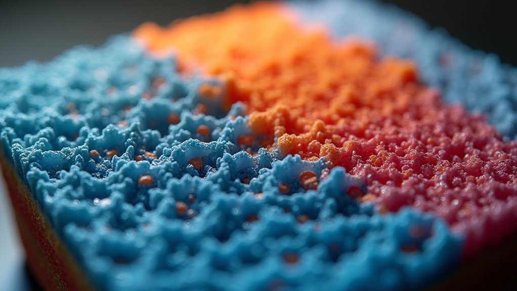
The technique works by adjusting infill density percentages throughout your model – typically ranging from 10% for lightweight areas to 100% for maximum strength zones.
This selective reinforcement guarantees your parts meet specific functional requirements while conserving material and reducing print time in less critical areas.
Selecting the Right Software for Variable Infill Settings
Your choice of slicing software directly impacts how effectively you can implement variable infill density in your 3D prints.
You’ll need to evaluate whether your current slicer supports advanced infill customization features, as not all software offers the same level of control over density variations.
Before committing to a particular program, you should compare key capabilities like modifier tools, infill pattern options, and ease of setup to guarantee it meets your specific printing requirements.
Software Compatibility Requirements
Since variable infill density requires sophisticated slicing capabilities, you’ll need software that can handle complex infill modifications beyond basic uniform settings.
Your chosen slicer must support advanced features like infill modifiers and regional density control to achieve different infill densities within a single print. The mesh type compatibility becomes essential when working with complex geometries that require varying structural support.
Important compatibility requirements include:
- Printer profile support – Verify your specific 3D printer model appears in the software’s database
- Firmware communication – Confirm proper G-code generation for your printer’s control board
- File format handling – Compatibility with STL, 3MF, and other mesh formats you’ll use
- Variable infill features – Built-in tools for creating infill regions and density modifiers
- Regular updates – Active development confirming continued printer compatibility and feature improvements
Feature Comparison Analysis
After identifying compatible software options, you’ll need to evaluate how each slicer handles variable infill functionality to make the best choice for your specific printing needs.
Ultimaker Cura stands out with its robust feature set, enabling custom printer profiles and region-specific infill adjustments.
You’ll find PrusaSlicer equally impressive with its intuitive 3D editor that lets you add modifiers directly to your models, giving you precise control over critical areas.
However, CuraLE doesn’t offer thorough variable infill support, so you’d benefit from upgrading to Ultimaker Cura instead.
PrusaSlicer’s fine-tuning capabilities particularly shine when you’re balancing print strength against material efficiency.
Don’t overlook community forums where you’ll discover shared troubleshooting solutions and best practices for optimizing your variable infill settings.
Creating Modifier Objects to Define Density Zones
You’ll create modifier objects in PrusaSlicer by right-clicking your model and selecting the modifier option to establish specific density zones.
Position cylinder-shaped modifiers precisely around critical areas like mounting holes where you need enhanced strength.
Once you’ve placed your modifiers, you’ll adjust the infill density percentage within each modifier’s settings to customize the internal structure for those targeted zones.
Positioning Cylinder Modifiers
When you need to strengthen specific areas of your print without adding unnecessary weight to the entire model, cylinder modifiers in PrusaSlicer offer precise control over infill density placement.
Right-click your model in the 3D editor and select ‘modifier,’ then choose ‘cylinder’ to create targeted infill zones. You’ll want to strategically position these modifiers around critical areas where structural integrity matters most.
Key positioning strategies include:
- Place cylinders around mounting holes to prevent cracking under fastener stress
- Position modifiers at connection points between different model sections
- Target areas that’ll experience repeated mechanical loading during use
- Focus on thin sections that might benefit from additional internal support
- Consider stress concentration points where forces naturally accumulate
After positioning, resize each cylinder to cover only necessary zones before re-slicing.
Adjusting Modifier Settings
Once you’ve positioned your cylinder modifiers, configuring their specific settings determines how effectively they’ll reinforce your model’s critical zones.
Click on each modifier to access its infill density parameters. You’ll want to increase the infill percentage considerably for areas requiring extra strength—consider 80-100% density around mounting holes compared to your base model’s 15-20%.
Don’t forget to adjust the infill pattern within modifiers; grid or cubic patterns provide excellent structural support for high-stress areas.
You can also modify other parameters like perimeters and top/bottom layers within these zones.
Take time to fine-tune these settings based on your specific application requirements, as proper configuration guarantees your critical areas receive the reinforcement they need.
Optimizing Base Layer Density for Structural Stability
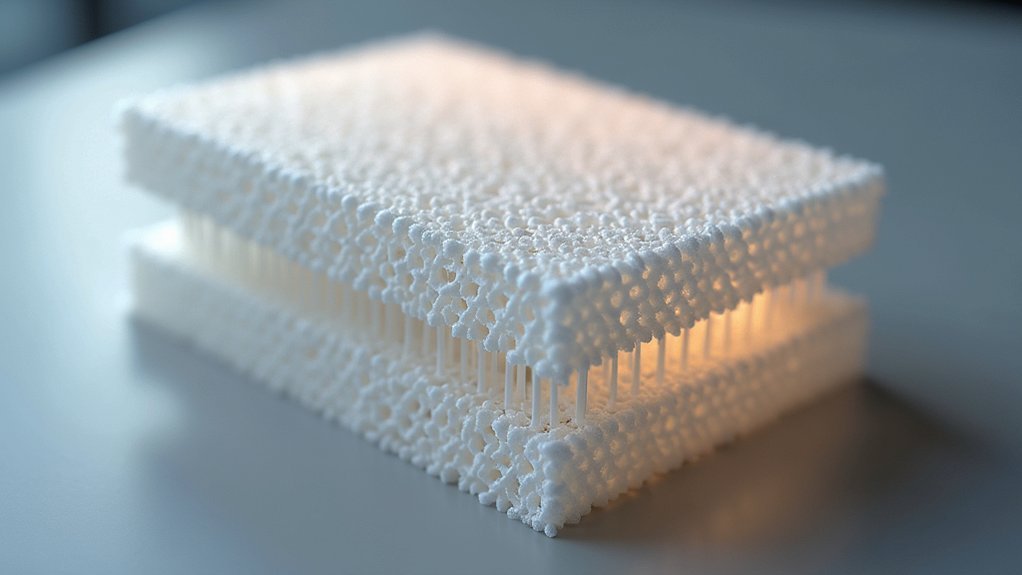
Since the base layer serves as your print’s foundation, optimizing its infill density becomes essential for achieving structural stability throughout the entire build.
You’ll want to increase your base layer infill density to prevent warping and guarantee proper bed adhesion. Setting this density between 30% to 100% creates a solid foundation that supports subsequent layers effectively.
Consider these optimization strategies for maximum structural stability:
- Set base layer infill density to 100% for critical functional parts requiring maximum strength
- Use denser infill patterns like solid grid or concentric designs to improve load-bearing capacity
- Increase base layer thickness beyond your standard layer height for enhanced stability
- Add extra perimeters to your first layer for improved adhesion and structural integrity
- Experiment with thicker first layers to reduce uneven surfaces and print failures
Gradually Reducing Infill Percentage in Upper Sections
You’ll achieve ideal weight reduction by implementing strategic layer height shift methods that gradually decrease infill density as your print progresses upward.
Support blocker implementation techniques let you define specific zones where infill changes occur, giving you precise control over material distribution throughout your model’s height.
Density customization per zone enables you to tailor infill percentages to match the structural requirements of each section, ensuring you’re not wasting material where it’s not needed.
Layer Height Transition Methods
While maintaining structural integrity remains paramount in your print’s foundation, altering to reduced infill percentages in upper sections offers significant material savings without compromising functionality.
You’ll need to implement smooth layer height changes that complement your variable infill strategy. Proper change methods guarantee your print maintains quality while optimizing efficiency.
- Configure slicer change settings to gradually alter layer heights from 0.2mm at the base to 0.1mm in detailed upper sections
- Start with 70% infill density in foundational layers, then reduce progressively to 15% in top regions
- Utilize visual preview tools to verify smooth density changes before printing
- Adjust print speeds when changing between different layer heights to prevent quality issues
- Test change zones on small models first to perfect your settings
Support Blocker Implementation Techniques
To gradually reduce infill density in upper sections, you’ll implement support blocker techniques that create custom-shaped regions within your slicing software.
Support blockers allow you to target specific areas with different infill percentages, enabling strategic strength adjustments where needed most.
Start by creating a support blocker around the upper section where you want reduced infill density. This technique noticeably decreases material usage while maintaining structural integrity for both aesthetic and functional parts.
You’ll achieve a lighter final product, perfect for weight-sensitive applications.
Configure the infill settings specifically for your blocked region through your slicer’s interface. Always monitor the slicing preview to verify that your infill modifications display accurately and won’t compromise your print’s overall stability before starting the printing process.
Density Customization Per Zone
Building on support blocker fundamentals, density customization per zone takes your variable infill strategy further by creating smooth gradients throughout your print’s height.
You’ll start with higher density at the base where structural strength matters most, then gradually reduce it as you move upward. This approach saves material while maintaining critical support where needed.
Using slicer software like PrusaSlicer or Cura, you can implement precise zone-based adjustments through modifiers. This technique reduces weight, minimizes warping risks, and decreases thermal stresses in upper sections.
- Start with 100% infill density at the base for maximum strength
- Gradually shift to 10-20% density in upper, less critical areas
- Use modifiers to define specific zones requiring different densities
- Preview slicing results to guarantee smooth density shifts
- Focus reinforcement on mounting points and structural areas
Combining Different Infill Patterns Within Single Prints
Although most 3D prints use a single infill pattern throughout the entire model, you can strategically combine different patterns within one print to optimize both performance and efficiency. Using slicer software like PrusaSlicer, you’ll employ modifiers to assign distinct patterns to specific regions. This approach lets you place honeycomb infill in load-bearing areas while using lighter grid patterns elsewhere.
| Area Type | Recommended Pattern |
|---|---|
| Load-bearing zones | Honeycomb/Triangular |
| Non-critical areas | Grid/Lines |
| Flexible regions | Gyroid/Cubic |
You’ll achieve significant material savings and faster print times by reserving complex patterns for structural features only. This method also improves dimensional accuracy by providing targeted internal support where needed, preventing warping in critical sections while maintaining efficiency throughout your print.
Testing Small Models Before Full-Scale Production
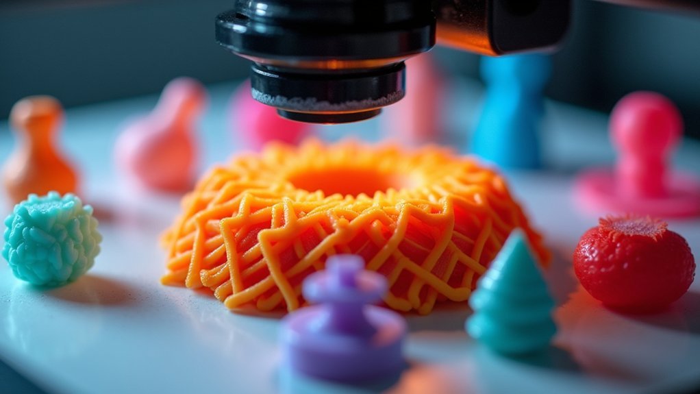
The most effective approach to perfecting your variable infill density settings involves creating small test models that validate your choices before committing to full-scale production. By printing small cubes or functional prototypes with different infill configurations, you’ll quickly identify ideal settings that balance strength and weight for your specific application.
These test prints reveal potential issues like warping or layer adhesion problems before they affect larger, more expensive projects. Small-scale testing provides valuable insights into how infill density affects print quality, dimensional accuracy, and overall durability. You can evaluate mechanical properties and performance without wasting materials on full-sized prints.
- Use standardized test cubes (20mm³) for consistent comparison across different infill densities
- Test infill ranges from 10% to 40% in 10% increments for baseline understanding
- Document printing times and material usage for each test configuration
- Perform stress tests on samples to evaluate structural integrity differences
- Compare surface finish quality between varying infill density levels
Balancing Strength Requirements With Material Conservation
When you’re designing parts with variable infill density, achieving the ideal balance between structural integrity and material efficiency requires strategic thinking about where strength matters most.
You’ll want to identify high-stress regions like mounting holes, load-bearing surfaces, and connection points, then reinforce these areas with higher infill percentages while keeping non-critical zones lightweight.
Start with 10-15% infill for general areas and increase to 50-80% where mechanical demands are highest. Honeycomb and gyroid patterns maximize strength without excessive material usage in dense regions.
This targeted approach reduces print weight and material costs while maintaining performance.
Modern slicer software like PrusaSlicer makes implementing variable density settings straightforward, letting you customize infill percentages throughout your model for peak strength-to-weight ratios.
Positioning High-Density Areas Around Critical Features
Building on this foundation of strategic infill planning, you’ll need to precisely position your high-density zones around the specific features that bear the most stress.
Focus on mounting holes, fasteners, and load-bearing connections where structural failures typically occur. You can use slicer software like PrusaSlicer to create modifier shapes—cylinders work well around holes—that customize infill density in targeted areas.
Prioritize critical stress points like mounting holes and fasteners by using cylindrical modifiers in your slicer to create targeted high-density zones.
Set these critical zones to 100% infill while maintaining lower densities like 30% elsewhere for peak material balance.
Don’t forget to adjust layer height and perimeter settings within modifiers to maximize adhesion and strength.
- Create cylindrical modifiers around mounting holes and fasteners
- Set 100% infill density for load-bearing areas
- Maintain 30% density in non-critical regions
- Adjust layer height within high-density modifiers
- Preview slicing results before printing
Monitoring Print Quality During Layer Transitions
As infill density changes between layers, you’ll need to watch your print carefully since these shifts often reveal weak points that can compromise your part’s integrity.
Focus on the first few layers after each change, as they’re most vulnerable to warping and misalignment when density changes considerably.
Before printing, use your slicer’s preview function to visualize how density adjustments will affect changes and guarantee smooth connectivity.
During printing, adjust speed and temperature settings to accommodate material flow modifications, which helps maintain quality and reduces defects.
Regularly inspect your prints for gaps or inconsistencies at change points.
These defects typically indicate problems with infill settings or printer calibration that you’ll need to address to achieve reliable results.
Frequently Asked Questions
What Is the Best Infill Density for 3D Printing?
You’ll want 15-20% infill for decorative prints and prototypes to save time and material. For functional parts needing strength, you should use 50-100% infill depending on mechanical stress requirements.
Is 40% Infill Too Much?
You’ll find 40% infill isn’t too much for functional parts needing strength and durability. However, it’s excessive for decorative prints where you’re prioritizing material savings and faster printing times.
Is 20% Infill Strong Enough?
You’ll find 20% infill adequate for decorative prints but insufficient for functional parts under stress. You should increase density to 30% or higher for load-bearing objects requiring structural integrity.
Is 10% Infill Enough on Reddit?
You’ll find Reddit users generally agree 10% infill works for decorative prints and prototypes, but you shouldn’t use it for functional parts needing strength or durability.


Leave a Reply