You can dramatically improve your 3D printing success by using thermal imaging to monitor hot end temperature distribution, analyze print bed heat uniformity, and detect cooling fan effectiveness. Check thermistor positioning accuracy, track layer adhesion through real-time thermal feedback, diagnose extruder heat creep, and prevent thermal runaway by watching for temperature spikes. These techniques transform guesswork into data-driven decisions that catch problems before they ruin your prints and enhance overall reliability through proactive monitoring.
Monitor Hot End Temperature Distribution During Print Operations

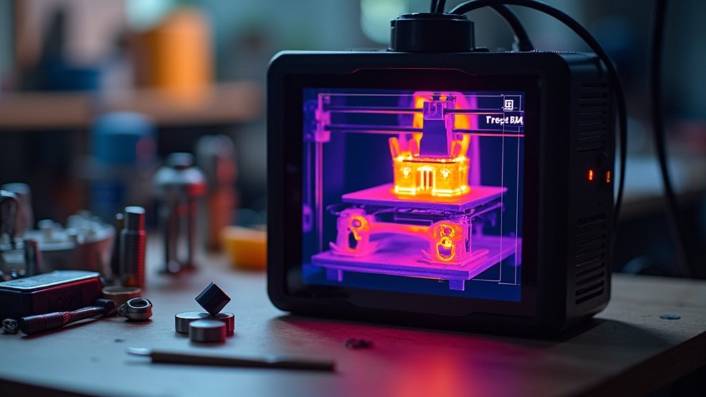
When you’re operating a 3D printer, thermal imaging cameras provide invaluable insights into your hot end’s temperature distribution that standard thermistors can’t deliver.
You’ll visualize hotspots and cold spots that directly impact extrusion quality, identifying issues invisible to traditional sensors.
Monitor real-time temperature variations with your thermal camera to guarantee consistent heating throughout print operations.
Real-time thermal monitoring ensures your hot end maintains consistent temperatures, preventing print failures before they occur.
You’ll catch thermal runaway situations immediately when unexpected spikes or drops occur, preventing potential damage from sensor malfunctions or heating element failures.
Target appropriate temperatures for your materials—PLA needs 190-220°C while PETG requires 220-250°C.
After activating part cooling fans, use thermal imaging to verify temperature stability remains intact.
This thorough monitoring approach prevents filament jams and maintains consistent flow rates essential for quality prints.
Analyze Print Bed Heat Uniformity Across the Surface
You’ll need to map temperature variations across your print bed’s entire surface to identify inconsistent heating patterns that can ruin print adhesion.
Start by detecting hot spots and cold zones using thermal imaging, then focus your analysis on specific calibration areas where you typically place your prints.
This systematic approach lets you pinpoint exactly where heating elements aren’t performing uniformly and adjust your setup accordingly.
Temperature Variation Mapping
Although your print bed’s heating element might appear to distribute heat evenly, thermal imaging reveals the hidden reality of temperature variations that can make or break your print quality.
Temperature variation mapping using thermal cameras exposes hotspots and cold spots across your bed’s surface, enabling targeted adjustments for better heat uniformity.
You’ll need a well-calibrated thermal camera to detect minor temperature discrepancies that impact adhesion and overall print quality.
These thermal images also show how part cooling fans affect bed temperatures, helping you optimize fan speeds to minimize adverse cooling effects.
Regular thermal assessments help you understand how different materials like PETG or PLA respond to bed temperatures, allowing fine-tuning for each filament type while diagnosing thermistor placement or heating system failures.
Hot Spot Detection
Three critical factors determine successful hot spot detection: camera positioning, measurement accuracy, and systematic analysis of your print bed’s thermal profile.
Position your thermal camera at multiple angles and distances to capture extensive coverage of the entire print bed surface. You’ll need to identify temperature variations exceeding 5°C from the average bed temperature, as these hot spots directly impact print adhesion and quality.
Monitor your bed’s thermal distribution continuously during printing to catch real-time fluctuations. When you detect problematic areas, implement corrective actions like repositioning prints or adjusting fan speeds.
- Steam rising from overheated zones while cooler areas remain perfectly still
- Bright orange-red patches glowing against cooler blue-green regions on your thermal display
- Invisible heat waves shimmering above malfunctioning heating elements
Calibration Zone Analysis
After identifying problem areas through hot spot detection, calibration zone analysis takes your thermal monitoring a step further by examining heat uniformity patterns across your entire print bed surface.
You’ll want to regularly analyze your calibration zone during initial setups using your thermal imaging camera, comparing images before and after heating to guarantee even distribution.
Pay close attention to your thermistor’s location relative to the print area, as its position greatly influences perceived bed temperature and can lead to inaccurate readings.
Experiment with different temperature settings while observing thermal images to determine ideal temperatures for various filament materials. This guarantees uniform heating across the entire surface, giving you the consistent foundation needed for successful prints.
Detect Cooling Fan Effectiveness and Airflow Patterns
One of the most revealing applications of thermal imaging involves monitoring your cooling fan’s performance and the resulting airflow patterns across your print bed.
Thermal cameras expose how airflow affects temperature distribution, revealing vital insights that standard monitoring can’t detect.
Standard temperature sensors only tell part of the story—thermal imaging reveals the hidden airflow dynamics affecting your entire print bed.
You’ll discover that larger prints don’t receive uniform cooling compared to smaller parts, creating uneven heating zones.
For PETG printing, maintain 30-40% fan speed to preserve ideal bed temperature without excessive cooling.
Monitor your thermistor’s location to guarantee it accurately reflects print area temperature rather than direct fan airflow.
- Visualize cool air streams creating distinct thermal boundaries across your heated print surface
- Watch temperature fluctuations ripple through different print zones as fan cycles activate
- Observe thermal shadows where larger objects shield portions of your bed from cooling airflow
Identify Thermistor Positioning and Heat Sensor Accuracy

While your printer’s control board relies on thermistor readings to regulate temperatures, thermal imaging reveals whether these sensors actually reflect real-world conditions across your print surface.
You’ll quickly spot if your thermistor’s positioned too far from the heating element, causing delayed temperature feedback that leads to inconsistent heating patterns.
Check your thermal camera display for temperature variations across the bed—significant differences indicate poor sensor placement or malfunction.
When thermistors drift or fail, you’ll see hot spots that don’t match the reported temperatures, increasing thermal runaway risks.
Ensure your thermistor connections remain secure and undamaged, as loose wiring creates temperature monitoring gaps.
Ideal thermistor placement produces uniform thermal readings, improving print quality while preventing dangerous overheating situations.
Track Layer Adhesion Through Real-Time Thermal Feedback
You can use thermal imaging to monitor temperature patterns across each printed layer, giving you immediate insight into how well your layers are bonding together.
The thermal camera reveals hot and cold spots that indicate whether your material is reaching ideal adhesion temperatures, typically 180-220°C for PLA.
Temperature Pattern Recognition
Several critical temperature patterns emerge during 3D printing that’ll reveal the quality of layer adhesion in real-time.
You’ll notice distinct thermal signatures when monitoring your prints through thermal imaging cameras. Temperature increases across successive layers indicate proper heat transfer and bonding, while sudden drops suggest adhesion failures. Your thermal camera will detect hotspots that warn of potential warping before visible defects appear.
Key patterns to recognize include:
- Uniform thermal gradients flowing smoothly from the nozzle down through recently deposited layers, resembling cascading warm ribbons
- Consistent bed temperature distribution maintaining that critical 60-85°C range for PETG, appearing as steady orange glowing zones
- Cooling fan effectiveness creating distinct thermal boundaries where part cooling creates sharp temperature shifts between heated and cooled regions
Layer Bond Visualization
When thermal cameras capture the moment each new layer meets the previous one, they’re revealing the invisible dance of molecular bonding that determines your print’s structural integrity.
Layer bond visualization through thermal imaging shows you exactly where adhesion succeeds or fails in real-time.
Strong bonds display consistent temperature patterns across your print, while weak adhesion creates telltale hotspots and temperature anomalies.
You’ll spot warping and delamination the instant they begin, allowing immediate parameter adjustments to save your print.
Monitor your thermal feedback to fine-tune print speed, extruder temperature, and cooling fan settings.
High-resolution thermal cameras provide the detailed insights you need for precise diagnosis.
This real-time layer bond visualization transforms guesswork into data-driven decisions, dramatically improving your print reliability.
Print Failure Prevention
While traditional 3D printing relies on post-failure analysis to understand what went wrong, thermal imaging transforms your approach by catching problems before they ruin your print.
You’ll spot temperature inconsistencies that threaten layer adhesion in real-time, allowing immediate adjustments to save your project. Thermal images reveal critical issues like hotend overheating or inadequate part cooling that would otherwise destroy hours of work.
Your thermal feedback loop enables precise extruder and bed temperature control, preventing warping and delamination before they start.
You can adjust fan speeds dynamically based on thermal data, maintaining ideal airflow for materials like PETG.
- Watch heat patterns flow across each layer like a thermal river
- See cold spots appear as dark islands disrupting adhesion
- Observe temperature gradients painting your print’s success story
Diagnose Extruder Heat Creep and Filament Flow Issues
Heat creep represents one of the most frustrating challenges you’ll face with your 3D printer, but thermal imaging transforms this invisible problem into something you can actually see and fix.
Point your thermal camera at the extruder during printing to monitor temperature distribution throughout the hotend assembly. You’ll quickly identify heat creep when thermal images reveal excessive temperatures climbing up the heat break into areas that should remain cool.
Watch for uneven temperature patterns that indicate poor heat transfer, and monitor your cooling fins for signs of inadequate airflow.
During filament retractions, observe thermal fluctuations that signal jamming issues. Document thermal profiles for different materials since each filament’s unique melting characteristics require specific temperature adjustments to prevent flow problems.
Prevent Thermal Runaway by Monitoring Temperature Spikes

Although thermal runaway might seem like a distant concern, it’s actually one of the most dangerous failures that can occur in your 3D printer, potentially causing fires or serious damage to your equipment.
Thermal imaging provides real-time monitoring to catch temperature spikes before they escalate into thermal runaway incidents. You’ll want to use high-resolution thermal cameras to visualize temperature distributions across your hotend and print bed, identifying dangerous hotspots immediately.
Key monitoring points include:
- Glowing red zones around the heater cartridge that indicate sensor malfunctions
- Bright yellow patches on cooling fans showing inadequate heat dissipation
- Orange streaks along wiring connections revealing electrical resistance heating
Regular thermal assessments guarantee your cooling systems function correctly and prevent extruder jams from causing excessive heat buildup.
Frequently Asked Questions
What Are the Best Practices for Thermal Imaging Cameras?
You should prioritize radiometric capabilities for accurate temperature measurements, guarantee your camera operates within relevant temperature ranges, use short integration times, calibrate regularly, and perform maintenance checks to identify overheating components.
Does Aluminum Foil Block Thermal Imaging?
Yes, aluminum foil blocks thermal imaging by reflecting infrared radiation instead of emitting it. You’ll get false readings because the foil’s reflective surface obscures actual temperature signatures underneath it.
How to Diagnose Heat Creep on a 3D Printer?
Monitor your hotend’s temperature gradient using a thermal camera to spot heat traveling up the filament path. Check if cooling fans work properly and verify there’s good thermal contact between components.
Which Factors Determine the Best Thermal Imaging Camera for an Inspection?
You’ll need to contemplate your required temperature range, desired image resolution, detector integration time for capturing rapid changes, available budget, and whether you need real-time monitoring capabilities for effective diagnostics.


Leave a Reply