STL orientation directly impacts your 3D print’s strength, surface finish, and production costs. You’ll achieve maximum strength when forces align parallel to layers, while perpendicular forces create weak points. Proper orientation minimizes support material needs, reduces print time, and improves surface quality by positioning critical features upward. Your first layer adhesion depends on maximizing contact area with the build platform. Different technologies like FDM and SLA require specific orientation strategies to optimize results and unveil advanced techniques.
Understanding the Impact of Print Orientation on Part Quality
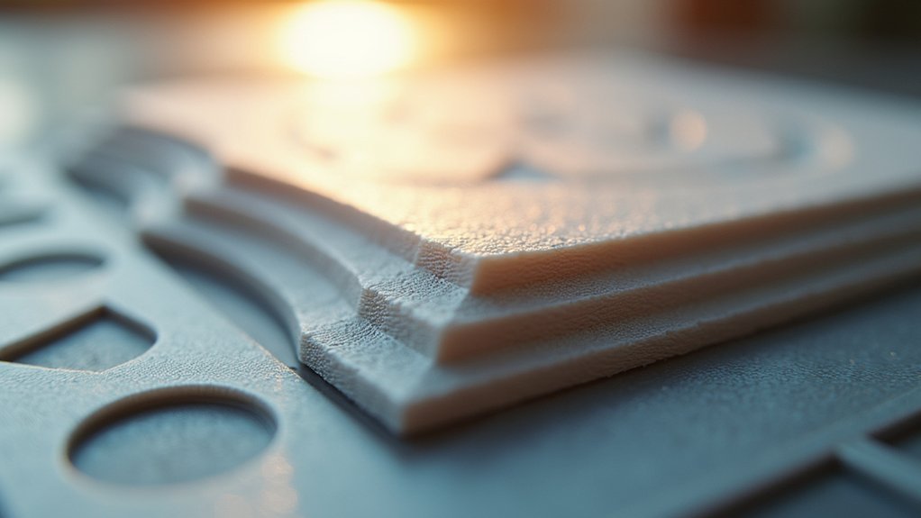
When you’re preparing an STL file for 3D printing, the orientation you choose directly impacts your part’s structural integrity and overall quality. Features printed along the Z-axis are typically weaker due to layer lines compared to those printed in the X and Y axes.
Your part orientation also affects surface finish visibility – horizontal surfaces provide smoother finishes, while angled builds may highlight imperfections.
You’ll need to take into account support material requirements when determining orientation. Minimizing support structures enhances surface finish and reduces post-processing efforts.
Critical features should face upward to achieve higher accuracy and better surface quality, as downward-facing features can suffer from support removal issues. Proper part orientation optimization improves mechanical performance and reduces print failure risks.
Strength and Structural Integrity Considerations
Beyond surface quality and support considerations, your STL orientation choices fundamentally determine how well your printed part withstands mechanical stress.
When tension forces act parallel to your layers, you’ll achieve maximum strength, but forces perpendicular to layers create dangerous weak points where delamination occurs.
Position critical features upward to enhance structural integrity and minimize layer separation risks. For compressive loads, horizontal orientations distribute stress more effectively across layers.
In FDM printing, you’ll get superior strength along X and Y axes compared to the weaker Z-axis direction due to layer adhesion limitations.
Proper orientation also prevents differential shrinkage and warping that compromise complex geometries during cooling, ensuring your part maintains its intended structural performance throughout the printing process.
Minimizing Support Material Requirements
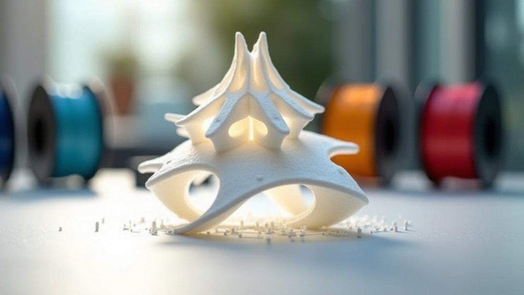
Since support structures add complexity, cost, and post-processing time to your prints, strategic STL orientation becomes your most powerful tool for eliminating unnecessary supports.
You can minimize support by positioning parts to leverage your printer’s natural bridging capabilities and optimizing surface areas that contact the build plate.
Smart orientation choices help you:
Strategic part positioning eliminates unnecessary supports, reduces post-processing time, and maximizes your printer’s natural capabilities for cleaner, more efficient prints.
- Position overhangs above 45 degrees to utilize bridging without supports
- Lay parts flat to distribute weight evenly and create stable prints
- Avoid complex geometries that demand extensive support structures
- Reduce surface scarring from support removal points
- Test multiple orientations to balance quality with material efficiency
Achieving Optimal Surface Finish Results
While reducing support material saves time and cost, the orientation you choose directly impacts your print’s surface quality and visual appeal.
You’ll achieve the best surface finish by orienting parts flat, which minimizes visible layer lines and creates smoother surfaces. Position critical features facing upward to enhance their appearance and guarantee superior quality on important areas.
Avoid building parts facing down when possible, as removing support structures often leaves surface scars that compromise glossy finishes.
Angled orientations typically highlight layer lines, reducing aesthetic quality considerably.
Communicate your surface finish requirements clearly during the design phase. This allows you to optimize orientation choices that balance both visual appeal and functionality, guaranteeing your final print meets your quality expectations.
Balancing Print Time and Material Costs
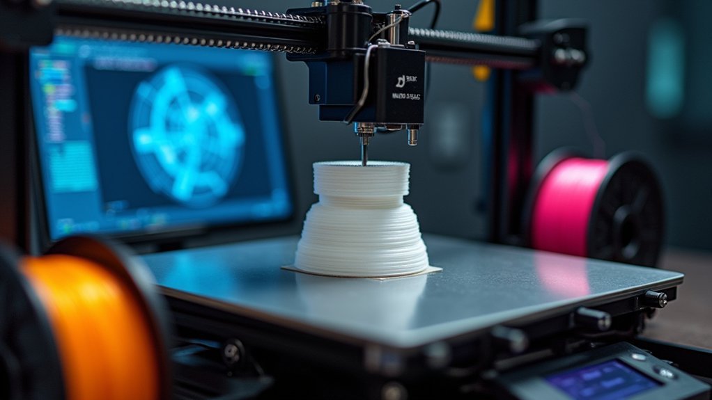
You’ll find that smart STL orientation directly impacts your bottom line by minimizing support material requirements and reducing overall print costs.
When you orient parts with excessive Z-height, you’re not just extending print time—you’re also driving up material consumption through necessary support structures.
Different 3D printing technologies present unique cost trade-offs, so you’ll need to evaluate how FDM, SLA, and SLS each respond to orientation changes when optimizing for both speed and material efficiency.
Support Material Optimization
When you’re aiming to reduce both material costs and print time, the orientation of your STL file becomes a critical factor in determining how much support material your 3D printer will need.
By strategically positioning your model, you’ll minimize the support material required while maintaining print quality.
- Position overhangs at 45 degrees or less to enable bridging without additional supports
- Orient parts horizontally when possible to reduce steep angles that demand extensive scaffolding
- Use visualization software to simulate different orientations before printing
- Analyze complex geometries to identify which surfaces truly need support structures
- Consider splitting large models into smaller sections with ideal individual orientations
Smart orientation choices directly translate to material savings and faster print times, making your 3D printing workflow more efficient and cost-effective.
Z-Height Cost Impact
Beyond support material considerations, your STL’s z-height directly impacts your printing budget through material consumption and build time. Every additional millimeter in z-height increases filament or resin usage proportionally, driving up costs per part in both FDM and SLA technologies.
You’ll notice shorter prints complete faster, reducing energy consumption and machine time expenses. When you optimize orientation to minimize z-height, you’re fundamentally balancing multiple cost factors. Lower builds require less material while decreasing printing duration.
However, don’t sacrifice part quality for height reduction alone. Smart orientation choices can simultaneously reduce z-height and improve surface finishes, eliminating expensive post-processing steps. Strategic positioning also minimizes support requirements, further cutting material costs and cleanup time.
Technology-Specific Trade-offs
Although orientation affects all 3D printing technologies, FDM and SLA present distinct trade-offs that’ll shape your material and time budgets differently.
In FDM printing, your print orientation choice directly impacts layer adhesion strength and support requirements. Minimizing height reduces print time but can weaken parts along layer lines. Conversely, vertical orientations strengthen critical load-bearing areas while extending print duration.
SLA technology offers different considerations where angled builds can minimize resin waste and support structures while maintaining structural integrity. Your slicing software becomes invaluable for visualizing these trade-offs before committing to a print.
- FDM flat orientations reduce support material costs but may compromise strength
- Vertical FDM builds enhance mechanical properties at longer print times
- SLA angled orientations balance material usage with structural performance
- Slicing previews help optimize print orientation decisions
- Post-processing time varies markedly based on chosen orientation
Layer Adhesion and Build Platform Stability
You’ll achieve the most reliable prints by prioritizing first layer stability through proper STL orientation.
When you position your model so that larger flat surfaces contact the build platform, you’re creating a foundation that resists warping and shifting during the printing process.
This platform contact optimization becomes critical for tall models with naturally small base areas, where you’ll need to modify the STL file to create artificial flat surfaces for maximum adhesion.
First Layer Stability
The foundation of any successful 3D print starts with proper first layer adhesion to the build platform. Your STL orientation directly affects first layer stability, determining whether your print succeeds or fails.
When you orient models with larger flat surfaces against the build platform, you’ll increase contact area and reduce warping risks. Tall prints with small bases need special attention – you can modify STL files to create flat bases or add support structures.
Consider these orientation strategies for ideal first layer stability:
- Position the largest flat surface of your model against the build platform
- Orient critical aesthetic features upward to minimize visible Z-axis layer lines
- Minimize overhangs that require supports near the first layer
- Create custom flat bases in CAD software for unstable models
- Use rafts or brims for additional adhesion on challenging geometries
Platform Contact Optimization
Building on proper first layer techniques, optimizing platform contact goes beyond simply placing flat surfaces down – it requires strategic thinking about how your model’s geometry interacts with the build surface throughout the entire print process.
Platform contact optimization involves maximizing the contact area between your model and build platform while considering the model’s structural integrity.
You’ll want to orient tall prints with small cross-sections to include broader bases, even if that means modifying your STL files.
Strategic orientation can distribute weight evenly across the platform, preventing layer separation and reducing warping risks.
Consider adding rafts or brims when your chosen orientation creates minimal contact points.
Technology-Specific Orientation Guidelines
Since each 3D printing technology operates through distinct mechanisms, you’ll need to tailor your STL orientation strategy to match the specific strengths and limitations of your chosen process.
For FDM printing, orient your parts in the XY plane whenever possible to maximize layer adhesion and overall strength. The directional nature of layer bonding makes Z-axis orientation considerably weaker for structural components.
- Position critical features facing upward in SLA printing to minimize support structures and achieve ideal surface accuracy.
- Consider build orientation carefully in powder bed fusion to influence part density and mechanical properties.
- Minimize support structures in PolyJet technology by strategic orientation to reduce material costs and improve print quality.
- Balance strength requirements against surface finish needs when determining ideal orientation.
- Evaluate part geometry and functional requirements before finalizing orientation decisions.
Common Orientation Strategies for Different Geometries
When you’re determining the best orientation for your STL files, different part geometries require distinct strategic approaches to achieve ideal print results.
For simple geometries, you’ll want to choose flat orientations that minimize support material requirements while enhancing surface finish and reducing post-processing time.
With cylindrical or elongated parts, vertical positioning aligns layers with applied forces, greatly improving structural strength against bending stresses.
Complex geometries benefit from angled positioning, which reduces support material needs while maintaining both aesthetics and structural integrity.
For intricate designs, you should test multiple orientations to optimize print quality and minimize layer visibility.
Multi-part assemblies require individual orientation strategies for each component to guarantee proper fit and quality.
Troubleshooting Orientation-Related Print Issues
Even with careful planning, you’ll encounter orientation-related problems that can compromise your print quality and structural integrity.
Despite meticulous preparation, orientation challenges will inevitably emerge, threatening both your print’s visual appeal and mechanical strength.
When your prints fail or exhibit defects, the orientation is often the culprit requiring immediate attention.
- Layer separation issues – Reorient parts to avoid stress concentration along Z-axis weak points
- Excessive support material usage – Rotate your model to minimize overhangs and reduce support requirements
- Visible layer lines – Adjust orientation to hide layer boundaries on critical surfaces
- Warping and distortion – Maintain consistent cross-sectional areas throughout print height to prevent differential shrinkage
- Poor surface finish – Test multiple orientations during slicing to find the ideal balance between support scarring and surface quality
Testing various orientations systematically helps you identify solutions that improve mechanical performance while reducing post-processing time.
Frequently Asked Questions
How Does Orientation Affect a 3D Print?
Your print’s orientation determines strength, surface quality, and support needs. You’ll get weaker parts with visible layer lines when critical features face sideways. Orient properly to minimize supports and maximize strength.
Which Orientation Is Best for 3D Printing?
You’ll find flat orientations work best for minimizing supports and achieving smooth surfaces. Choose vertical orientations when you need maximum strength along the Z-axis, or angled orientations for balanced results.
What Is the Best Orientation to 3D Print a Bolt?
You’ll get best results printing bolts vertically with threads aligned parallel to print layers. This orientation strengthens the bolt, reduces delamination risk, minimizes support needs, and guarantees accurate thread quality.
Why Is Print Orientation Important in SLA?
You’ll find orientation affects your SLA print’s strength, accuracy, and surface finish. Proper positioning minimizes layer weaknesses, reduces warping from differential shrinkage, and guarantees critical features face upward for better detail resolution.


Leave a Reply