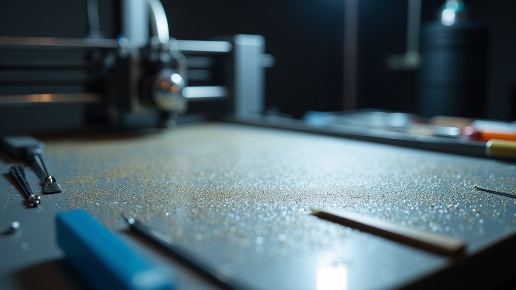
You’ll dramatically improve bed adhesion by optimizing your STL files before printing. Orient models with their largest flat surface on the build plate and scale them 5-10% to increase contact area—aim for at least 25 cm² of surface contact. Increase wall thickness to three times your nozzle diameter and add textured patterns or grooves to the bottom surface for enhanced grip. Use mesh repair tools to fix non-manifold edges and validate your geometry in slicer software first. These preparation techniques reveal even more advanced adhesion strategies.
Understanding STL File Geometry for Optimal Bed Contact
While many factors influence print success, your STL file’s geometry fundamentally determines how well your model adheres to the print bed.
You’ll want to maximize surface area contact by ensuring your model has a sufficiently large base. Analyze your geometry for problematic overhangs and sharp angles that reduce bed adhesion, then modify these features to create stability.
Use software tools to identify non-manifold edges or mesh holes that compromise printability. Orient your model so the largest flat surface sits on the bed, maximizing contact area.
Proper mesh analysis and strategic model orientation create optimal bed contact, ensuring your prints start strong and stay secured throughout the process.
Consider incorporating brims or skirts directly into your STL file design rather than relying solely on slicer settings. This approach increases the surface area touching your build plate, creating superior adhesion and preventing warping or dislodging during printing.
Model Orientation Strategies That Maximize First Layer Adhesion
Once you’ve optimized your STL geometry, strategic model orientation becomes your next critical step for achieving rock-solid first layer adhesion.
Position your model with the largest possible contact area touching the build plate – this dramatically reduces warping and detachment risks. When dealing with overhangs, angle them strategically to minimize support requirements that could interfere with your print surface bond.
Align your model to match your build plate’s natural contours, distributing weight evenly across the surface. For models with small footprints, consider adding a brim to expand the contact area and prevent shifting.
Keep tall features away from the bed level to avoid nozzle interference that compromises first layer adhesion. Smart model orientation transforms problematic prints into reliable successes.
Adding Support Structures and Bases During File Preparation
When your model’s footprint isn’t large enough to maintain solid bed contact, strategic support structures become essential anchors that prevent warping and detachment.
You’ll need to carefully plan these additions during file preparation to maximize adhesion while minimizing post-processing headaches.
Consider these three key approaches:
- Rafts – Create a stable foundation beneath your entire model, especially useful for complex geometries or warp-prone materials that struggle with direct print bed contact.
- Brims – Add extra outlines around your model’s base to increase surface area and anchor edges that might otherwise lift or curl during printing.
- Strategic placement – Position support structures to avoid excessive model contact, using adjustable density and patterns like grid or gyroid for ideal removal balance.
Scaling Adjustments to Improve Contact Surface Area
You can strategically scale your 3D model to maximize bed contact and prevent adhesion failures during printing.
Increasing your model’s base dimensions by 5-10% creates a more stable foundation, while calculating the ideal scale ratio guarantees you’re balancing adhesion needs with design integrity.
These scaling adjustments work particularly well for models with small footprints that struggle to maintain proper bed contact throughout the printing process.
Optimal Scale Ratios
If your model struggles with bed adhesion due to limited contact surface area, scaling adjustments can provide an effective solution.
You’ll want to find the sweet spot that maximizes your first layer’s bond without compromising your design’s integrity.
Here are the ideal scale ratios to take into account:
- 5-10% increase – This modest adjustment greatly enhances bed adhesion while maintaining design accuracy and preventing noticeable distortion.
- Maintain aspect ratio – Always scale uniformly across all dimensions to avoid warping that could actually worsen your contact surface quality.
- Focus on base width – Prioritize scaling that creates a wider footprint, or add a brim for narrow designs that need extra anchoring power.
These incremental changes create considerable improvements in first layer stability without sacrificing print quality.
Base Dimension Calculations
Three critical measurements determine whether your base dimensions will deliver the adhesion strength you need.
First, calculate your current contact surface area by measuring length times width of your model’s bottom face. If it’s below 25 cm², you’ll need to scale up your base dimensions by 10-20% to achieve ideal bed adhesion.
Second, verify your first layer height settings in your slicer – increasing this creates more surface contact with the print bed.
Third, adjust the first layer width to be 10-15% wider than normal layers.
These calculations guarantee your model maintains proper contact throughout printing.
Wall Thickness Modifications for Enhanced Stability
You can greatly improve your print’s bed adhesion by adjusting wall thickness settings in your slicer.
Increasing wall thickness to at least 1.2mm or three times your nozzle diameter creates a more robust structure that’s less likely to warp or detach during printing.
Fine-tuning your perimeter count works hand-in-hand with thickness adjustments to optimize the balance between material usage and structural stability.
Optimal Wall Thickness Settings
Wall thickness stands as one of the most critical factors determining your print’s structural integrity and bed adhesion performance.
When you configure ideal wall thickness settings, you’ll dramatically improve bed adhesion while achieving superior print quality. The relationship between wall thickness and layer height directly impacts how stress distributes throughout your model, helping reduce warping during the printing process.
Consider these essential guidelines for ideal settings:
- Set wall thickness to multiples of your nozzle diameter – use 1.2mm for 0.4mm nozzles to enhance layer adhesion.
- Apply 2-3 times nozzle diameter for detailed prints – maintains dimensional accuracy and supports intricate features.
- Utilize variable thickness features – strengthen critical areas while optimizing material usage in less essential regions.
These adjustments create stronger foundations that resist lifting and warping.
Perimeter Count Adjustments
While wall thickness forms the foundation of print stability, perimeter count adjustments take this concept further by giving you precise control over how many outer shells surround your print’s interior.
Increasing your perimeter count strengthens the first layers considerably, creating better adhesion between your print and the build surface. This enhanced wall thickness helps distribute heat evenly across the print bed adhesion zone, reducing warping risks.
You’ll want to set at least three perimeters for larger prints to maximize contact area with your bed.
For small footprints or intricate designs, experiment with four or more perimeters instead of the typical default of two. This adjustment not only delivers better adhesion but also improves your print’s overall strength and durability for functional applications.
Identifying and Fixing Problematic Mesh Issues
Before your printer can deliver perfect first layers, your 3D model’s mesh must be structurally sound and free from digital defects that can sabotage bed adhesion.
Even perfect print settings won’t compensate for a flawed STL file. Non-manifold edges, holes, and self-intersections create unpredictable printing behavior that compromises your foundation layer.
Here’s how to ascertain mesh integrity:
- Run automatic diagnostics – Use mesh repair tools in your slicer or dedicated applications like Meshmixer to identify overlapping faces, inverted normals, and structural gaps that cause print fails.
- Check wall thickness – Inspect your model for excessively thin sections that create weak points and compromise bed adhesion during the critical first layers.
- Optimize orientation – Position your model to minimize stress concentration on initial layers while maintaining structural integrity throughout the print.
Creating Custom Brims and Rafts in Your STL Design
You can build custom brims and rafts directly into your STL file instead of relying solely on slicer-generated supports.
Understanding brim design fundamentals helps you create the right perimeter width and thickness for your specific model’s adhesion needs.
Optimizing your raft structure involves balancing base layer thickness with easy removal features to guarantee both stability during printing and clean separation afterward.
Brim Design Fundamentals
Although most slicers automatically generate brims and rafts, designing these adhesion aids directly into your STL file gives you complete control over their dimensions and placement. This approach guarantees optimal print bed adhesion for your specific model requirements.
When implementing brim design fundamentals, follow these essential guidelines:
- Width specifications – Create brims that extend 5-10 mm beyond your model’s base to maximize contact area without affecting the final print dimensions or requiring excessive material removal.
- Thickness optimization – Design your brim or raft with 0.2-0.4 mm thickness to balance strong adhesion with easy post-processing removal once printing completes.
- Geometry consideration – Position brims strategically around your model’s perimeter, ensuring they don’t interfere with critical features or intricate details that could compromise print quality.
Raft Structure Optimization
While standard slicer-generated rafts work for most prints, creating custom raft structures directly within your STL file releases advanced adhesion capabilities that automatically adapt to your model’s unique geometry and weight distribution.
You’ll achieve superior raft structure optimization by designing base layers that extend beyond your model’s footprint, creating maximum contact with the print bed. Focus on thickness adjustments that enhance first layer adhesion while preventing warping through substantial surface area coverage.
Include subtle tapers on raft edges to simplify removal without compromising stability during printing. Your custom raft design should integrate seamlessly with slicing software settings, ensuring proper G-code generation.
This approach delivers consistent adhesion performance across various print bed materials and conditions, particularly benefiting models with challenging geometries or minimal base contact areas.
Hollowing Techniques That Maintain Bed Adhesion
Hollowing your 3D models saves material and reduces print weight, but it can compromise the essential first-layer adhesion that keeps your prints stuck to the bed.
Strong first-layer adhesion becomes critical when hollowing models, as reduced material contact with the print bed can lead to failed prints.
You’ll need strategic approaches to maintain that important bond between your model and the build surface.
- Preserve your base thickness – Keep the bottom surface at least 2-3 mm thick to provide solid contact area with the print bed. This stable foundation guarantees proper bed adhesion even when the rest of your model is hollowed.
- Add internal support structures – Include cross-bracing or internal supports within hollowed sections to prevent deformation during printing, which protects first layer integrity.
- Maintain proper wall thickness – Keep walls no thinner than your nozzle diameter and use gradual changes to avoid sudden alterations that could affect print bed temperature distribution and adhesion.
Surface Texture Modifications for Better Grip
When your prints struggle to stick despite perfect leveling and temperature settings, modifying the surface texture of your model’s base can provide the extra grip you need.
Adding small grooves or patterns to your 3D model’s bottom surface creates enhanced contact with the print bed, greatly improving bed adhesion during those critical initial layers.
You’ll find that a roughened texture increases surface area, reducing warping and lifting risks.
Experiment with stippled or dimpled designs to distribute adhesive forces evenly across the print bed.
Apply slight chamfers at your model’s edges to prevent curling while improving first layer contact.
For models with small footprints, incorporate wider bases or increased contact areas in your STL design, providing additional stability that prevents dislodgement during printing.
File Resolution Settings That Impact Print Success
Your STL file’s resolution settings directly determine whether your print will succeed or fail at the bed adhesion stage.
File resolution affects how your printer interprets the model’s geometry, which influences first-layer contact with the build surface.
Here’s how to optimize your STL file for better bed adhesion:
- Set layer heights between 0.1-0.3mm – Lower values create smoother surfaces but require more processing power, while higher values may compromise print quality on detailed areas touching the bed.
- Balance polygon count appropriately – Higher polygon counts improve surface smoothness but create larger files that slow slicing and can cause print failures.
- Use mesh repair tools before slicing – Fix non-manifold edges and holes that can disrupt first-layer adhesion and cause unexpected printing behaviors.
Pre-Print Validation Tools and Mesh Repair Methods
Even perfectly configured file settings won’t save your print if underlying mesh problems exist in your STL file.
You’ll need effective mesh repair methods to fix non-manifold edges and holes that compromise bed adhesion. Use software tools like Meshmixer or Netfabb to diagnose and repair these issues before printing.
Perform pre-print validation using your slicer software to verify proper model orientation and first layer adhesion to the print bed.
For complex geometries with small footprints, slice models into multiple parts for better bed adhesion control. Analyze your model’s base thickness and add skirts or brims directly in the slicer to enhance first layer contact.
Regularly test different repair methods, filling gaps and reinforcing weak structures to guarantee adequate stability and surface area for effective bed adhesion.
Frequently Asked Questions
How to Make Bed Adhesion Better?
You’ll improve bed adhesion by cleaning and leveling your print bed, setting proper bed temperature, slowing first layer speed to 20-30 mm/s, using adhesion aids, and maintaining stable ambient temperature.
What Is a Quick Tip for Improving Bed Adhesion During the First Layer?
You’ll want to slow your first layer speed to 20-30 mm/s and increase the extrusion width by 20-30%. This gives filament more time to bond properly with your print bed.
Should You Increase or Decrease Bed Temperature for Better Adhesion?
You should increase bed temperature for better adhesion. Higher temperatures reduce cooling speed and minimize warping, especially for materials like PETG. However, don’t exceed recommended ranges to avoid excessive sticking.
What Is the Best Adhesion for 3D Printing Beds?
You’ll achieve ideal bed adhesion by maintaining proper heated bed temperatures, using adhesive aids like glue sticks, adding brims or rafts, choosing appropriate build surfaces, and keeping your print bed clean.

Leave a Reply