To calibrate powder layer thickness for metal printing, you’ll need to adjust your spreader gap settings within the 20-100 micron range using precision measurement tools like micrometers and laser systems. Start by maintaining environmental controls with humidity below 40% and stable temperatures within ±2°C. Conduct test prints with varying gap configurations to establish baseline metrics, then measure density and porosity to optimize settings. Regular calibration every 90-180 days guarantees consistent part quality and prevents fusion defects that compromise structural integrity.
Understanding Powder Layer Thickness in Metal Additive Manufacturing

When you’re working with metal additive manufacturing, powder layer thickness becomes one of the most critical parameters that’ll determine your final part’s quality and structural integrity. This thickness typically ranges from 20 to 100 microns, directly influencing your printing quality throughout the entire build process.
You’ll find that thinner layers generally improve detail resolution and reduce porosity in your parts, while thicker layers enhance build speed but may compromise precision.
The uniformity and consistency of your powder layers are essential to prevent defects like lack-of-fusion porosity, which can severely compromise mechanical properties.
Consistent powder layer uniformity prevents lack-of-fusion porosity that weakens mechanical properties in metal additive manufacturing.
Understanding how variations in layer thickness affect the melting process helps you optimize your printing parameters for superior results and reliable part performance.
Essential Equipment and Tools for Layer Thickness Calibration
Three fundamental categories of equipment form the backbone of effective powder layer thickness calibration in metal additive manufacturing.
First, you’ll need precision measurement tools like micrometers or laser measurement systems to assess layer uniformity and thickness accurately. These instruments provide the detailed measurements necessary for proper calibration.
Second, high-resolution height-mapping metrology systems deliver extensive data on powder bed topology, ensuring consistent layer thickness throughout your build process. This essential equipment monitors surface variations that could affect print quality.
Third, automated powder bed calibration systems streamline operations by measuring and adjusting thickness in real-time without production interruptions.
Don’t forget supporting tools like sieving apparatus for uniform powder granule sizes. Schedule calibration checks every 180 days to maintain ideal performance.
Pre-Calibration Setup and Environmental Considerations

Before you begin calibrating powder layer thickness, you’ll need to establish proper environmental controls and verify your equipment setup.
Start by ensuring your workspace maintains consistent temperature and humidity levels, as fluctuations can affect powder behavior and measurement accuracy.
Next, confirm that all calibration tools are clean, properly positioned, and functioning correctly to avoid measurement errors during the process.
Environmental Control Requirements
Environmental control forms the foundation of successful powder layer thickness calibration, as even minor deviations in humidity, temperature, or contamination levels can compromise your entire printing process.
You’ll need to maintain humidity levels below 40% and keep temperatures stable within ±2°C to prevent moisture absorption that affects powder flow.
Store your metal powders in sealed containers to minimize oxidation and preserve the quality of the powder throughout calibration.
Install real-time monitoring systems to track environmental conditions continuously, enabling immediate adjustments when deviations occur.
These environmental control requirements directly impact layer thickness consistency, so you can’t afford to overlook temperature fluctuations around your printing area that alter powder behavior and distribution patterns.
Equipment Setup Verification
With your environmental parameters properly established, you’ll need to verify that your equipment setup meets the precise requirements for accurate layer thickness calibration.
Start by inspecting your powder container’s seal integrity to prevent oxidation that compromises layer consistency. Implement proper handling techniques, including systematic sieving to eliminate particle size variations that affect powder layer uniformity.
Next, calibrate your 3D printer’s recoater system to guarantee even powder distribution across the build platform. Uneven recoating directly impacts layer thickness accuracy, so verify blade alignment and travel speed settings.
Check that your powder storage remains in a controlled, dry environment to prevent moisture absorption.
Finally, establish monitoring protocols for temperature and humidity fluctuations in your printing area, as these environmental changes influence powder behavior and layer deposition consistency.
Selecting Optimal Powder Characteristics for Layer Formation
Foundation of any successful metal printing operation starts with selecting powders that exhibit the right characteristics for consistent layer formation.
You’ll need to focus on particle size distribution between 20-50 microns to achieve ideal layer thickness and effective melting. Evaluate your metal powders’ flowability by examining their shape and surface characteristics, guaranteeing uniform deposition without clogging issues during recoating.
Pay close attention to powder morphology, specifically sphericity and angularity, as these factors directly impact packing density and flow behavior.
Store your powders in low-humidity environments to prevent moisture absorption that disrupts layer formation.
Before beginning any build, conduct pre-build tests to assess powder bed thickness and uniformity. This prevents defects like lack-of-fusion porosity and guarantees proper layer adhesion throughout your printing process.
Spreader Gap Adjustment Techniques and Best Practices
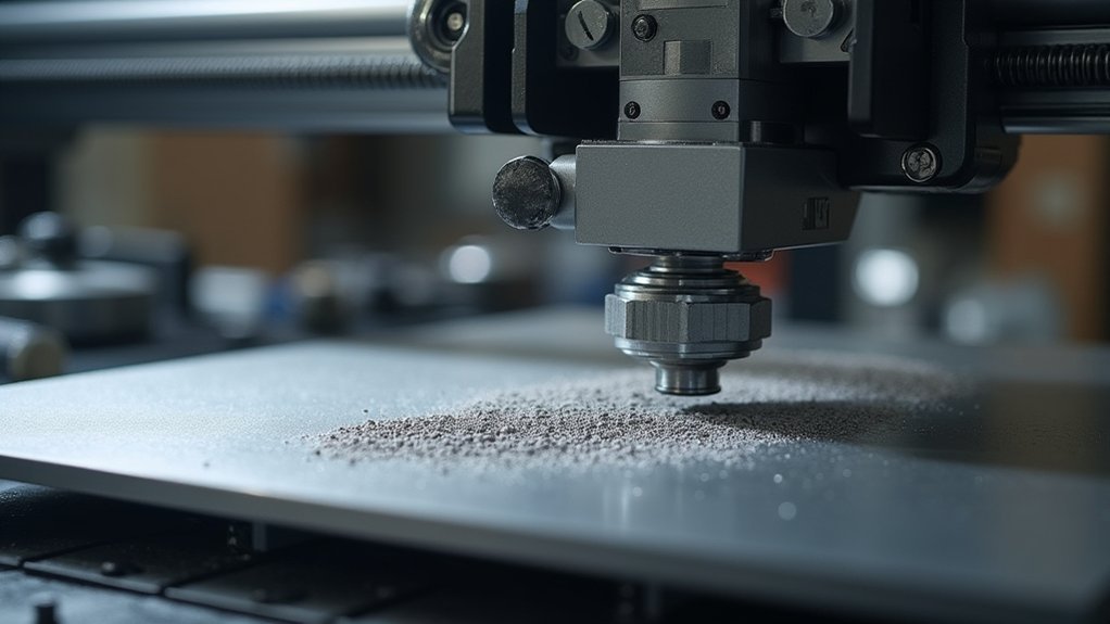
You’ll need precise gap measurement methods to determine your current spreader position before making any adjustments to the powder layer thickness.
Once you’ve established baseline measurements, you can follow systematic adjustment procedures that account for your specific powder characteristics and target layer parameters.
Finally, you must implement quality verification protocols to confirm that your gap adjustments are producing the uniform layer density required for successful metal printing.
Gap Measurement Methods
When calibrating your metal printer’s spreader gap, you’ll need precise measurement techniques to achieve the critical 100-200 micron distance between the recoater blade and powder bed. Two primary methods dominate gap measurement: feeler gauges and laser distance sensors.
| Method | Accuracy | Cost | Best Use Case |
|---|---|---|---|
| Feeler Gauges | ±10 microns | Low | Manual calibration |
| Laser Sensors | ±5 microns | High | Automated systems |
| Contact Probes | ±8 microns | Medium | Precision verification |
| Optical Systems | ±3 microns | Very High | Production environments |
Before production builds, conduct test measurements using known powder thickness samples to verify your spreader gap settings. Automated gap measurement systems reduce manual errors and maintain consistent layer thickness throughout printing. Regular calibration prevents blade wear from affecting your measurements, ensuring ideal powder distribution and print quality.
Adjustment Procedure Steps
Start your spreader gap adjustment by powering down the printer and allowing all heated components to reach room temperature.
Access the spreader mechanism and locate the adjustment screws or digital controls. Use precision feeler gauges to measure the current spreader gap, targeting 100-300 microns depending on your powder specifications.
Make incremental adjustments of 10-20 microns at a time, checking measurements at multiple points across the build platform width. Verify layer thickness uniformity using your height-mapping metrology system after each adjustment.
Run a test spread cycle to confirm even powder distribution before finalizing settings. Document your final spreader gap configuration for future reference.
This systematic approach guarantees peak print quality and prevents costly reprints due to inconsistent powder layers.
Quality Verification Protocols
Once you’ve completed your spreader gap adjustments, implementing robust quality verification protocols guarantees your settings deliver consistent results across production runs.
Start by conducting test prints with varying gap configurations to establish baseline performance metrics for your specific materials. Document each spreader gap adjustment alongside corresponding print outcomes, creating a thorough database for future reference.
Deploy high-resolution height-mapping metrology systems to monitor powder layer topology in real-time during the printing process. These tools provide immediate feedback on layer uniformity and detect deviations before they compromise part quality.
Establish systematic check procedures that include measuring powder bed consistency at multiple points across the build platform. Your quality verification protocols should include reviewing layer adhesion, surface finish, and dimensional accuracy.
Regular calibration validation ensures your spreader gap settings maintain peak performance throughout extended production cycles.
Test Print Protocols for Layer Thickness Validation
The foundation of accurate layer thickness calibration lies in systematic test print protocols that validate your settings across multiple variables.
Systematic test protocols form the cornerstone of precise layer thickness calibration across multiple critical variables.
You’ll need to conduct test prints with layer thickness ranging from 30 to 100 microns, using calibration patterns like simple geometric shapes to assess adhesion, surface finish, and dimensional accuracy.
Your validation protocol should include:
- Density and porosity measurements – Document how different layer thickness settings affect part density and internal structure.
- Non-destructive testing evaluation – Use ultrasonic testing to identify internal defects without damaging test specimens.
- Standards compliance analysis – Compare results against industry specifications to ascertain quality requirements are met.
This systematic approach guarantees you’ll identify ideal layer thickness settings for your specific materials and design requirements.
Measurement Methods for Evaluating Layer Uniformity
Multiple measurement techniques enable you to accurately assess layer uniformity in metal printing, each offering distinct advantages for quality control.
Optical methods using high-resolution imaging capture your powder bed’s surface profile to evaluate thickness consistency effectively. You’ll find laser scanning techniques particularly valuable, as they provide precise powder layer thickness measurements and detect variations as small as 10 microns in the z-axis.
For thorough analysis, non-destructive X-ray computed tomography reveals internal porosity and layer density, giving you insights into potential defects.
Height-mapping metrology systems offer real-time monitoring capabilities, ensuring consistent layer uniformity throughout your printing process.
These measurement methods work together to maintain ideal powder layer thickness, with regular calibration recommended every 180 days for sustained print quality.
Parameter Optimization Based on Calibration Results
Once you’ve gathered calibration data, you’ll need to adjust key printing parameters to achieve ideal layer uniformity.
Start by fine-tuning your laser power settings to match the measured powder thickness variations across the build platform.
You’ll also want to enhance your recoating speed and revisit your layer thickness settings to guarantee consistent powder deposition throughout the entire printing process.
Laser Power Adjustments
When calibrating laser power for metal printing, you’ll need to systematically adjust energy output to achieve ideal powder melting and maintain consistent layer thickness. Start with power settings between 100-300 watts, depending on your metal powder type and desired layer specifications.
Your calibration process requires these essential steps:
- Measure melt pool dimensions – Monitor both size and depth to guarantee proper fusion without over-melting.
- Implement real-time thermal monitoring – Track the melt pool’s temperature profile for dynamic power adjustments.
- Document all calibration data – Record power settings and results to establish reliable baselines for future builds.
You’ll prevent lack of fusion porosity by fine-tuning through iterative testing. Use thermal feedback to maintain effective layer density across multiple builds, ensuring repeatable quality standards for your metal printing operations.
Layer Thickness Settings
Optimized laser power settings work hand-in-hand with precise layer thickness parameters to achieve consistent metal printing results.
You’ll need to adjust your layer thickness between 20-100 microns based on your specific technology and material requirements. Balance this setting with printing speed to prevent lack-of-fusion porosity while maintaining ideal material properties.
Use height-mapping metrology systems to monitor your powder bed topology in real-time, making data-driven adjustments as needed.
Thinner layers improve surface finish but reduce printing speed, while thicker layers increase throughput but may compromise detail resolution. You should recalibrate these settings every 90 days to maintain industry standards.
Remember that layer thickness directly affects how your laser energy interacts with the powder, influencing final part density and mechanical strength.
Recoating Speed Optimization
After establishing your ideal layer thickness parameters, you’ll need to fine-tune recoating speeds to maintain that precision throughout your printing process.
Your calibration results will reveal the best recoating speed by evaluating powder flowability and layer density. Typically, speeds between 10-30 mm/s work best, depending on your powder characteristics and printer capabilities.
Monitor your recoater’s performance using these key strategies:
- Implement height-mapping metrology systems to track layer thickness uniformity and adjust speeds dynamically during printing.
- Conduct frequent recoater calibration to prevent worn components from creating streaks that compromise layer quality.
- Deploy automated speed adjustments based on real-time calibration data to enhance production efficiency.
This systematic approach guarantees consistent layer thickness while minimizing defects like lack-of-fusion porosity, ultimately improving your overall part quality in metal additive manufacturing.
Troubleshooting Common Layer Thickness Issues
Although metal printing technology has advanced considerably, you’ll still encounter layer thickness issues that can compromise your final parts. Lack-of-fusion porosity represents the most common problem, typically stemming from insufficient layer thickness or uneven powder distribution that creates weak spots throughout your build.
To address these inconsistencies, you’ll need to regularly calibrate your recoater system. Worn recoaters create streaks that directly impact layer quality, so replacement is essential when performance degrades.
Implement height-mapping metrology systems to monitor your powder bed continuously and catch variations before they affect print quality.
Remember to adjust layer thickness settings based on your specific material requirements, as different metals need varying thicknesses for ideal melting and bonding.
Calibrate your powder bed every 180 days to compensate for thermal expansion effects.
Quality Control Standards for Powder Layer Consistency
When establishing quality control standards for powder layer consistency, you must implement systematic measurement protocols that assure your metal printing operations meet industry specifications.
Your calibration schedule should follow NASA’s recommended 180-day assessment intervals to maintain ideal layer thickness between 20-40 microns.
Essential quality control protocols include:
- Height-mapping metrology systems – Deploy real-time topology measurement tools to identify inconsistencies during printing.
- Non-destructive testing procedures – Utilize ultrasonic testing methods to detect internal defects caused by variable layer thickness.
- Industry compliance frameworks – Adhere to ASTM and ISO guidelines for critical applications.
Regular calibration prevents porosity issues and assures reliable fusion throughout your printing process.
You’ll minimize defects by maintaining consistent powder bed uniformity and implementing these standardized quality control measures across all metal additive manufacturing operations.
Maintenance Schedules for Sustained Calibration Accuracy
Maintaining sustained calibration accuracy requires three critical maintenance intervals that directly impact your metal printing success.
Establish powder bed calibration every 180 days to guarantee consistent layer thickness, though you should check more frequently due to recoater wear.
Schedule optics inspection and calibration every 90 days since drift affects layer melting accuracy in L-PBF processes.
Implement height-mapping metrology systems to assess powder bed topology before and during builds, preventing lack-of-fusion porosity issues.
Use automated calibration processes that capture extensive data for real-time monitoring and adjustments.
Document all calibration results and trends over time – this data informs your preventative maintenance schedules and helps predict when adjustments are necessary, assuring your metal additive manufacturing systems maintain peak performance.
Frequently Asked Questions
What Is Z Calibration?
Z calibration’s the process where you’ll adjust your build platform’s height to guarantee proper distance from the powder bed, preventing layer thickness issues that’d cause defects in your metal prints.
What Is the First Layer Calibration of Print?
You’ll adjust your printer’s initial layer thickness to guarantee proper powder adhesion and melting. This critical calibration step prevents fusion defects and establishes the foundation for quality metal parts throughout your build.
What Is the 45 Degree Rule for 3D Printing?
You’ll find the 45-degree rule means overhangs steeper than 45 degrees from vertical need support structures. Without supports, you’ll get sagging or collapsed features since there’s insufficient material underneath.
How to Tell if a Nozzle Is Too Low?
You’ll notice excessive powder compression, uneven distribution, and visible scratches on the build platform. The nozzle drags through powder, creating inconsistent layer thickness and increasing lack-of-fusion porosity in your prints.
Leave a Reply