You’ll achieve professional-quality prints from your multi-extruder setup by following a systematic 10-step calibration process that addresses each extruder’s unique characteristics and material requirements. Start by understanding your system type (direct vs. Bowden), gather essential tools like digital calipers and printer control software, then measure current E-steps using M503 commands. Test filament extrusion with marked 100mm segments, calculate new E-steps values, and save settings permanently to EEPROM. Fine-tune flow rates for each material type and validate performance through thorough testing that’ll reveal your printer’s full potential.
Understanding Direct Vs Bowden Multi-Extruder Systems
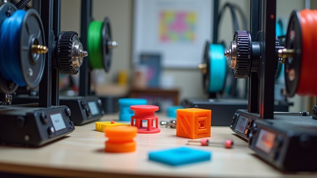
Before you begin calibrating your multi-extruder setup, you’ll need to understand whether you’re working with direct or Bowden systems since each requires different approaches.
Direct extruders mount directly on the hotend, giving you immediate control over filament extrusion. This setup excels with flexible filaments and reduces slippage risks, but adds weight to your print head.
Direct extruders deliver instant filament control and excel with flexible materials, though they increase print head weight.
Bowden systems position the extruder motor away from the hotend, using PTFE tubes to guide filament. While this reduces print head weight, you’ll face potential retraction issues and feeding inconsistencies due to the longer filament path.
For extruder calibration, direct systems need precise measurements because of their immediate response, while Bowden setups require adjustments for tube friction and extended filament travel distances.
Gathering Essential Tools and Software for Calibration
Before you begin calibrating your multi-extruder setup, you’ll need to gather specific hardware components and set up essential software tools.
Your hardware arsenal should include precision measuring instruments like calipers, a reliable USB cable for printer connectivity, and a marker for filament measurements.
On the software side, you’ll want to install programs like Pronterface or MatterControl while familiarizing yourself with key G-code commands such as M92 and M500.
Required Hardware Components
Five essential tools will determine whether your multi extruder calibration succeeds or fails.
These required hardware components form the foundation for precise measurements and accurate adjustments when you calibrate your extruder.
You’ll need a digital caliper or ruler for measuring filament diameter before and after extrusion.
Mark your filament clearly with a permanent marker to track exactly how much material passes through during testing.
Pronterface software enables direct communication with your printer via USB, allowing you to send G-code commands and monitor real-time responses.
Access your printer’s EEPROM settings to permanently save new E-steps values.
Without this capability, you’ll lose calibration data after power cycles.
Finally, maintain reliable hotend temperature control since different filament materials require specific temperatures for ideal flow rates during calibration procedures.
Essential Software Setup
Three critical software components must work together seamlessly for successful multi extruder calibration. Your essential software setup requires printer control software like Pronterface or MatterControl to communicate directly with your printer. You’ll also need firmware that supports EEPROM settings for saving calibration values permanently.
| Software Component | Primary Function |
|---|---|
| Pronterface/MatterControl | Direct printer communication |
| EEPROM-enabled firmware | Save calibration settings |
| G-code terminal | Send commands (M92, M500) |
| Measuring software | Track filament precision |
| Configuration utility | Manage multiple extruders |
Before starting calibration, verify your printer’s firmware supports essential G-code commands. You’ll use M92 to adjust Extruder Steps values and M500 to save configurations. Connect your printer via USB and test communication by sending basic commands through your chosen control software.
Connecting Your Printer and Accessing Extruder Settings
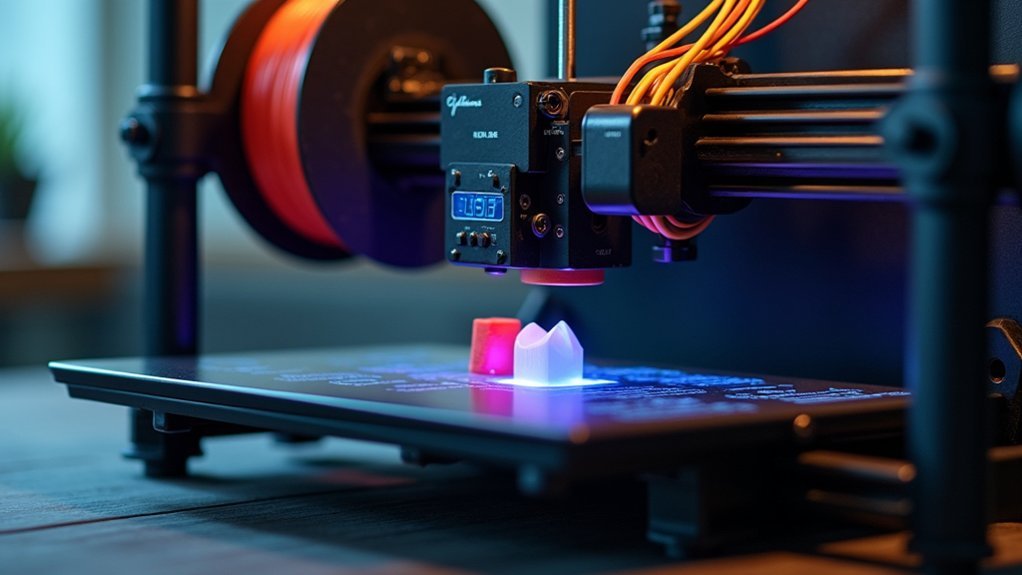
Once you’ve gathered your tools and materials, you’ll need to establish a connection between your 3D printer and computer using a USB cable.
Open Pronterface software to access your printer’s control interface and settings. Select the correct COM port in Pronterface to establish communication between your computer and printer.
Use the M503 command in the terminal to retrieve current extruder settings, including E-steps values for each extruder. This information shows you the correct amount of filament each extruder currently extrudes per step.
Before starting calibration, verify your hotend reaches the appropriate temperature for your filament type.
Familiarize yourself with essential G-code commands: M92 for setting E-steps and M500 for saving changes to EEPROM.
These commands will effectively manage your extruder settings throughout the calibration process.
Measuring Current E-Steps for Each Extruder
Before making any adjustments to your multi-extruder system, you’ll need to determine the current E-steps value for each extruder to establish a baseline for calibration.
Connect your printer to control software like MatterControl or Pronterface, then retrieve existing E-steps using the M503 command.
Mark exactly 100mm of filament from each extruder’s entry point using a ruler or caliper.
Switch to relative mode with M83, then command each extruder to extrude the marked length using G1 E100.
Measure the actual amount of filament extruded and compare it to your expected 100mm.
Document these values separately for each extruder, as hardware variations can cause different E-steps requirements between extruders.
Performing the Filament Extrusion Test
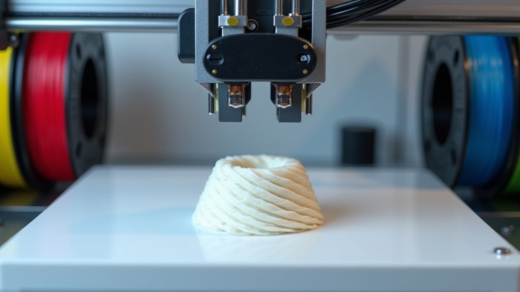
Now that you’ve established baseline measurements for each extruder, you’ll perform the actual filament extrusion test to determine accurate E-steps values.
Begin by marking a 100mm length on your filament from the entry point of each extruder. This reference point guarantees precise measurement during calibration.
Mark a precise 100mm reference point on your filament from each extruder’s entry to ensure accurate calibration measurements.
Execute the G-code command `G1 E100 F100` to extrude 100mm of filament at reduced speed, minimizing slippage and improving accuracy.
After the extrusion completes, measure the remaining filament from your marked point to determine actual distance extruded.
Calculate new E-steps using: New Steps/mm = (Current Steps/mm) x (100 / Measured Length).
Document this value in your printer’s EEPROM with `M92 Exxx.xx`, then save permanently using `M500`.
Calculating New E-Steps Values Using the Formula
Two critical factors determine the accuracy of your E-steps calculation: the precision of your measurements and the correct application of the formula.
Use this formula to calculate your new E-steps: New Steps/mm = (Old/Current steps/mm) x [100 / (measured distance filament traveled)]. If your current E-steps value is 93 and you measured 101.3mm of extruded filament, your new E-steps would be 91.80.
Follow these essential steps for accurate calculations:
- Measure precisely – Small discrepancies in the measured distance filament traveled create significant errors.
- Apply the formula correctly – Double-check your math before updating firmware settings.
- Validate immediately – Extrude 100mm again to confirm your new E-steps produce the expected results.
Always verify your adjustments work properly.
Programming Updated Settings Into Printer Memory
Once you’ve calculated your new E-steps values, you’ll need to program these settings into your printer’s memory to make them permanent.
Start by using the M92 command to set the new steps per millimeter for each extruder. For example, type “M92 E415.2 T0” for your first extruder and “M92 E420.8 T1” for your second extruder.
After programming updated settings into printer memory, execute the M500 command to save everything to EEPROM permanently.
Always verify your changes by running M503 to retrieve current E-steps values and measure from the end of your calibration marks.
If you switched to relative movement mode (M83) during testing, return to absolute mode using M82.
Consider adding these values to your slicer’s start G-code as backup.
Adjusting Flow Rates for Each Material Type
You’ll need to establish unique flow rate settings for each material in your multi-extruder setup, as PLA typically performs well at 100% while flexible filaments often require 90-95% to prevent over-extrusion.
Start your calibration process around 95-100% flow rate and make incremental adjustments of 1-2% until you achieve ideal layer adhesion and print quality for each material type.
Consider boosting your first layer flow rate by 5-10% for improved bed adhesion, then fine-tune the remaining layers based on your specific material’s behavior.
Material-Specific Flow Settings
When different materials pass through your extruder, they’ll behave uniquely due to their distinct viscosity and thermal properties, making material-specific flow adjustments crucial for consistent print quality.
Flexible filaments typically require a 5-10% flow rate reduction compared to standard PLA or ABS to prevent over-extrusion and filament slipping. You’ll need to fine-tune these settings through systematic testing and documentation.
Here’s your approach to enhancing material-specific flow settings:
- Start with 1% incremental adjustments when switching between materials, using this as your baseline for calibration.
- Conduct test prints for each filament type to evaluate layer adhesion and surface finish quality.
- Document your ideal flow rate settings for each material to streamline future printing processes and guarantee consistent results.
This methodical approach eliminates guesswork and creates reliable printing profiles.
Fine-Tuning Percentage Adjustments
Most materials require flow rate adjustments between 90% and 110% of your baseline settings, with these precise percentage tweaks serving as the difference between mediocre and exceptional print quality.
You’ll typically need to reduce initial flow rates by 1% to 6% after your first few layers for ideal adhesion. PLA performs best at 95-98% flow rates, while ABS often requires slight increases to maintain proper layer bonding.
When switching filaments, you must reevaluate these settings through test prints since diameter variations and composition differences dramatically affect extrusion consistency.
Monitor your first layer closely and adjust flow rates dynamically during printing. These fine-tuning percentage adjustments will immediately improve your results when you reduce initial line width or layer height to prevent over-extrusion.
Testing Print Quality With Calibration Models
Once you’ve completed the initial calibration settings, specialized calibration models become your primary diagnostic tools for evaluating multi-extruder performance.
Specialized calibration models serve as essential diagnostic tools for identifying multi-extruder performance issues beyond standard calibration capabilities.
These test prints reveal critical issues with color mixing, layer adhesion, and extrusion consistency that standard calibration can’t detect.
Focus on these essential testing approaches:
- Varying infill patterns and densities – Print models with different infill configurations to assess how each calibrated extruder maintains consistency across sections.
- Dimensional accuracy measurements – Evaluate overhangs and bridges to determine performance under challenging conditions.
- Visual inspections – Look for under-extrusion gaps or over-extrusion buildup that indicates flow rate problems.
Use these results to adjust your slicer’s flow rate settings, especially when working with different filament types that require specific fine-tuning.
Fine-Tuning Extrusion Speed and Temperature Settings
After completing your calibration tests, you’ll need to optimize each extruder’s speed and temperature settings for consistent, high-quality output.
Start by reducing extrusion speeds up to 50% from your baseline settings. Then systematically adjust temperatures within each filament’s ideal range—PLA between 190°C-220°C and ABS between 230°C-260°C.
Fine-tune your flow rates between 94%-100% in your slicer software to eliminate over-extrusion while maintaining proper material deposition.
Optimal Speed Calibration Methods
Two critical factors determine successful multi-extruder calibration: extrusion speed and temperature settings that work in harmony with your specific filament types.
Make certain you’re implementing ideal speed calibration methods to achieve consistent results across all extruders.
Here’s your systematic approach:
- Reduce extrusion speed to 50% during calibration tests to prevent filament slipping and guarantee accurate measurement of extruded lengths.
- Use G-code commands like G1 E100 F50 to control extrusion speed during tests, allowing precise monitoring of filament flow and consistency.
- Document all adjustments to extrusion speed and temperature settings, as these factors vary considerably between different filament types and brands.
Monitor flow rates regularly, making minor adjustments of 1-2% to improve layer adhesion and overall print quality.
Temperature Control Per Extruder
Since each filament material demands its own thermal sweet spot, you’ll need to calibrate temperature settings individually for every extruder in your multi-extruder setup.
Start by printing temperature towers at 5°C intervals to identify each material’s ideal range. Watch for signs like oozing or stringing that indicate excessive heat, while poor layer adhesion suggests insufficient temperature.
Use a thermocouple or thermal camera for precise nozzle readings, guaranteeing accurate temperature control across all extruders.
Don’t overlook the relationship between heat and speed—higher temperatures often require slower extrusion rates for proper material flow.
Test different combinations systematically, documenting results for each filament type. This methodical approach guarantees consistent quality from every extruder.
Flow Rate Adjustment Techniques
Precise flow rate calibration determines whether your multi-extruder prints achieve professional quality or suffer from under-extrusion and inconsistent layers.
You’ll need to measure the actual amount of filament extruded against commanded lengths to identify necessary adjustments.
Start your calibration process with these essential steps:
- Baseline Testing – Use slow feed rates (G1 E100 F50) during initial calibration to prevent filament slippage and motor step loss.
- Progressive Adjustment – Begin at 100% flow rate for first layers, then gradually decrease to 94% for improved adhesion and quality.
- Documentation Strategy – Record flow rate settings between 95-100% alongside print outcomes for different materials and extruder combinations.
Regular measurement and documentation help you establish ideal flow rates for each extruder configuration.
Frequently Asked Questions
Do I Need to Calibrate Extrusion Every Time?
You don’t need to calibrate extrusion every print. You should recalibrate when changing filament types, experiencing extrusion issues, modifying hardware, or performing major maintenance every few months.
What Is the Formula for Extruder Steps?
You’ll calculate new extruder steps using this formula: New Steps/mm = (Old Steps/mm) x [100 / (measured distance filament traveled)]. This adjusts your printer’s extrusion accuracy based on actual measurements.
In What Order Should You Calibrate Your 3D Printer?
You should calibrate your 3D printer in this order: level the bed first, then calibrate individual extruders one at a time, adjust E-steps separately, and finally perform test prints to verify everything’s working correctly.
How to Perfectly Calibrate Ender 3?
First, you’ll level your bed properly using paper method. Next, calibrate your extruder by measuring 100mm filament, using M503 to check E-steps, then adjusting with M92 command before saving settings.

Leave a Reply