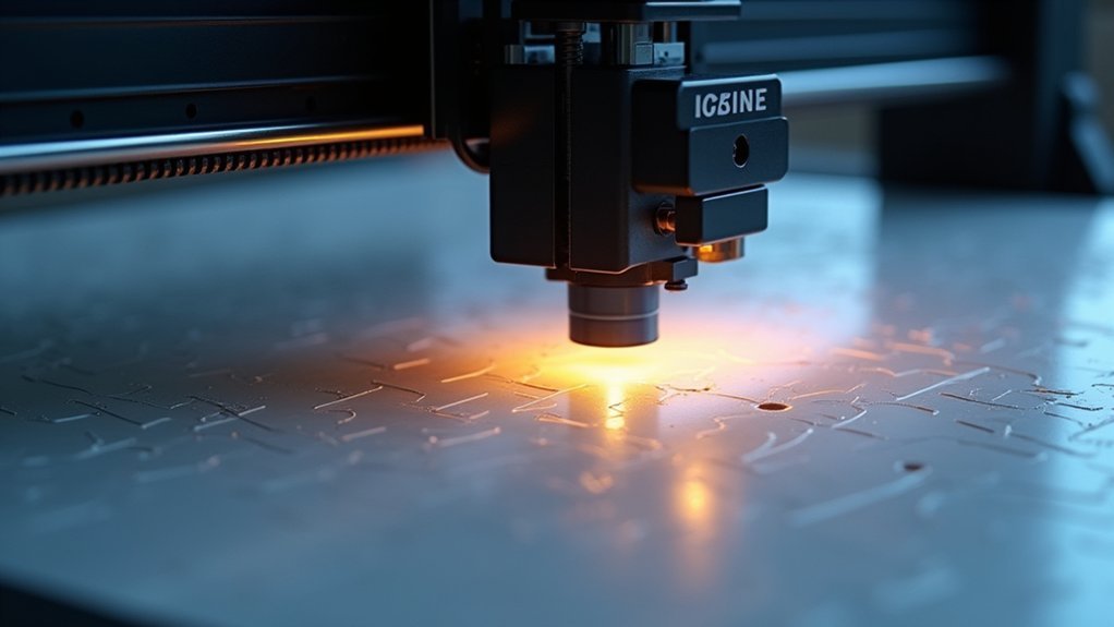
You’ll find the most effective large format bed leveling solutions include eddy current electromagnetic systems that scan 500mm beds in 80 seconds with 0.5μm accuracy, piezoelectric load cells detecting forces under 10mN, and inductive proximity sensor networks for simultaneous height mapping. Capacitive distance arrays, optical laser measurement systems, and strain gauge monitoring provide sub-micron precision, while multi-sensor hybrid detection combines technologies for enhanced accuracy. Real-time firmware compensation and manual mesh calibration complete your extensive toolkit for achieving perfect first layers on expansive print surfaces.
Eddy Current Electromagnetic Sensing Systems

Precision becomes critical when you’re working with large format 3D printers, where even minor bed irregularities can ruin hours of printing time.
Eddy current electromagnetic sensing systems offer a contactless solution that’s perfect for beds measuring 400–500mm or larger. These sensors generate magnetic fields that induce currents in your metal print bed, measuring distance variations with incredible accuracy—down to 0.5 μm in some cases.
You’ll appreciate the speed advantage, as these systems can scan a 500mm bed in roughly 80 seconds. Since there’s no physical contact, you won’t deal with probe wear or surface damage. This contactless measurement eliminates risks of probe drag or mechanical wear that commonly plague traditional leveling systems.
The sensors aren’t affected by heated beds or thermal expansion, ensuring consistent first-layer adhesion across your entire print surface while reducing setup complexity.
Piezoelectric Load Cell Force Detection
While electromagnetic sensing excels at contactless measurements, piezoelectric load cell force detection takes a different approach by measuring the actual contact forces between your nozzle and print bed.
Piezoelectric sensors measure actual nozzle-to-bed contact forces, offering a direct detection approach unlike contactless electromagnetic methods.
You’ll find these sensors generate voltage signals only during dynamic force changes, enabling precise detection of the exact moment your nozzle touches the surface. They’re incredibly sensitive, detecting contact forces under 10 mN while remaining rugged and affordable for large format applications.
You can implement piezo sensors as dockable probes or mount them directly under your bed. They’ll even detect contact quality differences, like contaminated versus clean nozzles. The conditioning circuitry cost is higher compared to other sensor technologies, but the robust accuracy justifies the investment.
However, you’ll need proper signal conditioning with high-impedance amplifiers, and slow contacts mightn’t trigger consistently since static pressure won’t generate output.
Inductive Proximity Sensor Networks

When you’re implementing inductive proximity sensor networks for large format beds, you’ll need to establish a multi-sensor array configuration that strategically positions sensors across your bed’s surface for thorough height mapping.
Your network communication protocols must handle multiple sensor inputs simultaneously, whether through multiplexing or independent processing channels that feed into your printer’s control board.
You’ll also face calibration and synchronization challenges, ensuring all sensors in your network provide consistent readings and maintain proper timing coordination for accurate mesh bed leveling. For optimal performance, connect your sensors to a 12V power supply rather than drawing power directly from your control board to ensure adequate voltage levels for reliable operation.
Multi-Sensor Array Configuration
Multi-sensor array configurations revolutionize large format bed leveling by deploying multiple inductive proximity sensors across your print bed’s surface to capture extensive height data simultaneously.
You’ll arrange sensors in grid patterns optimized to cover critical bed areas while minimizing blind spots. This approach eliminates the time-consuming sequential probing typical of single-sensor systems.
Configure your array spacing based on bed dimensions and desired mesh density—tighter spacing increases accuracy but requires more sensors.
You’ll need firmware supporting dense probe grids beyond basic 3×3 configurations to handle the increased data volume. Proper calibration involves setting reference heights and compensating for sensor-to-sensor offsets.
Mount sensors rigidly to maintain consistent measurement geometry, and implement signal conditioning to reduce electromagnetic interference for reliable operation. The first layer quality directly impacts your entire print success, making accurate multi-sensor bed mapping essential for professional results.
Network Communication Protocols
Implementing multiple sensors across your large format bed creates the immediate challenge of establishing reliable communication between each sensor and your printer’s control system.
You’ll need to choose between several proven protocols depending on your setup requirements. I2C and SPI work well for shorter distances with simpler wiring, while UART offers straightforward point-to-point communication. For longer spans or noisy environments, consider Modbus or CAN protocols, which provide superior noise immunity through differential signaling.
Your communication approach affects both responsiveness and reliability. Continuous polling gives you constant status updates but increases network traffic.
Interrupt-driven acquisition responds only when sensors detect changes, reducing bandwidth while maintaining quick response times. You can also implement embedded processing at sensor nodes to filter noise and preprocess data before transmission, minimizing false triggers and improving overall system performance. These sensors operate through electromagnetic induction to detect metallic surfaces without requiring physical contact with the bed.
Calibration and Synchronization
Precision becomes your greatest asset when calibrating inductive proximity sensor networks across large format beds.
You’ll need to establish proper Z-offset values and map multiple probing points to compensate for bed warping. Start with manual baseline leveling, then fine-tune using sensor feedback for ideal accuracy.
Synchronization guarantees all sensors report consistent measurements across your network.
You must coordinate probe timing to prevent physical interference while maintaining full bed coverage. Filter data to harmonize readings and account for response time variations between sensors.
Environmental factors affect your calibration stability.
Temperature fluctuations alter metal conductivity and sensor response, requiring regular recalibration. Secure sensor mounting prevents vibration-induced errors, while firmware integration enables automatic calibration routines and adaptive noise filtering for reliable performance. Inductive sensors create a topological map that tracks the actual metallic build surface rather than the print bed itself.
Capacitive Distance Measurement Arrays

You’ll find capacitive distance measurement arrays offer superior precision for large format bed leveling through strategically positioned multi-point sensor networks that detect even minute surface irregularities.
These arrays can measure both normal and shear forces across your entire print bed, providing extensive deformation mapping that traditional single-point sensors can’t match. The sensors achieve remarkable interfacial toughness of over 1000 J·m, preventing delamination issues that commonly plague conventional sensing systems under mechanical stress.
However, you’ll need robust temperature compensation methods since capacitive sensors are sensitive to thermal variations that naturally occur during large format printing operations.
Multi-Point Sensor Networks
When you’re dealing with large-format 3D printers, multi-point sensor networks revolutionize bed leveling by deploying an array of capacitive distance sensors across your print surface.
These sensors measure nozzle-to-bed gaps at multiple locations simultaneously, creating detailed surface topography maps that reveal unevenness and tilt patterns you’d miss with single-point systems.
You’ll position sensors in grid patterns—typically four or more spread evenly across your build area.
The firmware aggregates these measurements to generate height maps, enabling real-time Z-axis adjustments during printing. This mesh bed leveling approach provides enhanced accuracy for complex surface mapping across large format printers.
This dynamic compensation addresses local variations rather than assuming a flat surface, dramatically improving first layer adhesion and dimensional accuracy.
Your printer can now adapt to build plate irregularities as they’re detected, ensuring consistent results across large print beds.
Temperature Compensation Methods
Although capacitive sensors excel at non-contact distance measurement, they’re inherently susceptible to temperature variations that can throw off your bed leveling accuracy on large-format printers.
Your heated bed’s thermal expansion and the sensors’ temperature-dependent drift create measurement errors that compromise first layer adhesion.
You’ll need to implement temperature compensation by integrating thermistors alongside your capacitive elements to monitor local variations.
Apply real-time software corrections that adjust capacitance-to-distance conversion based on current thermal data.
Calibrate your sensor arrays at multiple temperatures to create lookup tables for accurate compensation.
Consider self-calibration routines during warm-up phases and temperature-stable components to minimize drift. Always perform mesh calibration at your target printing temperature rather than at room temperature to ensure consistent baseline measurements.
Integrate these compensation algorithms directly into your firmware for seamless operation without manual intervention.
Manual Mesh Point Calibration Methods
Manual mesh point calibration offers the most precise control over large format bed leveling, though it demands patience and methodical execution.
You’ll establish accurate Z-height references across your entire print surface by systematically adjusting individual mesh points.
Here’s your step-by-step approach:
- Prepare thoroughly – Clean your bed, home all axes, and set proper Z-offset before starting calibration.
- Position strategically – Use a 3×3 to 5×5 grid pattern covering corners and center areas for thorough mapping.
- Adjust incrementally – Move to each mesh point using G29 S1 commands, then fine-tune Z-height in 0.01mm steps with feeler gauges.
- Verify consistently – Re-check critical points and print test patterns to confirm leveling quality.
This method compensates for bed irregularities that automatic systems might miss on larger surfaces. Consider establishing faulty regions where probing consistently produces inaccurate results due to bed surface defects or irregularities.
Software-Driven Adaptive Leveling Algorithms
You’ll achieve superior results with software-driven adaptive leveling that performs real-time mesh compensation throughout your print job, continuously adjusting Z-height based on your bed’s topography map.
These advanced algorithms can integrate data from multiple sensors simultaneously, combining probe measurements with strain gauges or accelerometers to detect even subtle bed deformations during heating cycles.
When you’re working with large format printers, this dynamic approach compensates for thermal expansion and mechanical flex that static leveling methods simply can’t address. The system creates a denser mesh by probing only the specific area where your part will print, resulting in faster calibration and more precise surface mapping.
Real-Time Mesh Compensation
While traditional bed leveling relies on mechanical adjustments, real-time mesh compensation takes a software-driven approach that continuously adapts to your bed’s surface irregularities during printing.
This algorithm creates a virtual 3D map of your print bed, then interpolates between mesh points to smoothly adjust Z-axis movements as your print head moves across the surface.
For large format printing, this technology offers significant advantages:
- Compensates for pronounced surface irregularities up to 0.4mm or more across large beds
- Reduces setup time by automating height corrections without manual adjustments
- Maintains consistent first layer quality over the entire build area
- Works with beds that can’t be perfectly leveled mechanically due to size constraints
However, accuracy depends on thorough initial probing and proper mesh resolution. Regular mesh recalibration is necessary to maintain optimal performance as environmental conditions and bed surfaces can change over time.
Multi-Sensor Data Integration
Beyond single-sensor approaches, multi-sensor data integration represents the cutting edge of large format bed leveling technology.
You’ll achieve superior accuracy by combining inductive, capacitive, and optical sensors with force-sensitive resistors to create extensive bed topology maps. Your firmware algorithms collect these multi-point data streams and calculate dynamic Z-axis offsets for each coordinate during printing.
Advanced systems like Unified Bed Leveling (UBL) let you probe only relevant print areas, optimizing both time and precision.
Through sensor fusion, you’ll compensate for individual sensor limitations while mathematical models process stepper movements with real-time feedback. Load cells in newer systems enable automatic Z height setting by detecting direct nozzle contact with the bed surface.
This approach enables weighted averaging algorithms that maintain consistent nozzle height across expansive surfaces, dramatically reducing failed prints from leveling issues on large-format beds.
Multi-Sensor Hybrid Detection Systems
Large-format 3D printers benefit greatly from multi-sensor hybrid detection systems that combine different sensor technologies to overcome the limitations of individual sensing methods.
You’ll get enhanced accuracy by cross-verifying bed height data from multiple sources simultaneously, which is essential for detecting complex surface irregularities across extensive print areas.
These systems typically integrate:
- Force sensing nozzles that detect the slightest contact while doubling as Z-axis endstops
- Capacitive sensors for non-contact detection using electric field changes
- Inductive sensors that identify metal build plates through magnetic fields
- Real-time fusion algorithms that merge data streams for precise bed mapping
You’ll need robust data processing frameworks to manage synchronous sensor input effectively. Advanced systems can provide 360-degree measurement coverage to ensure comprehensive monitoring of the entire print bed surface.
Commercial applications like MudMax and Horizon demonstrate how these hybrid systems reduce manual intervention while improving print consistency.
Optical Laser Distance Measurement
Optical laser distance measurement represents a significant advancement in precision bed leveling technology, offering sub-micron accuracy through coherent light detection systems.
You’ll benefit from time-of-flight or phase-shift measurements that create real-time surface profiles without physical contact, eliminating mechanical wear on sensors. When you integrate laser sensors into your printhead assembly, you can generate automated mesh data faster than manual probing methods.
However, you must consider that bed surface reflectivity and texture affect signal quality, requiring proper calibration routines. Environmental factors like vibration and ambient light can introduce measurement noise.
You’ll need firmware compatibility and protective enclosures to shield sensors from debris. Despite higher initial costs, laser systems deliver superior resolution and repeatability compared to capacitive or inductive alternatives, making them ideal for large format applications. Temperature stabilization becomes critical for consistent measurements, as thermal fluctuations can introduce variability in sensor output that affects overall system reliability.
Strain Gauge Bed Monitoring Solutions
Strain gauge bed monitoring systems detect mechanical deformation in your printer’s bed structure, offering a fundamentally different approach than optical measurement methods.
These sensors convert mechanical strain into electrical signals through amplifier modules like HX711, allowing precise mapping of bed irregularities.
Key advantages of strain gauge solutions:
- Continuous monitoring – You’ll get real-time feedback during print jobs rather than static measurements.
- Environmental resistance – Unlike optical methods, they’re not affected by dust, lighting changes, or visual obstructions.
- Structural insight – You can detect frame flex and thermal stresses beyond just bed geometry.
- High sensitivity – They detect minute deformations that other systems might miss.
However, you’ll need careful calibration and proper mounting to guarantee accurate readings and reliable performance. Running bed leveling multiple times helps verify consistent results and identifies potential probe accuracy issues.
Real-Time Firmware Compensation Systems
While traditional bed leveling focuses on physical adjustments, real-time firmware compensation systems take a software-first approach that dynamically corrects Z-axis height during printing.
You’ll need to generate a mesh using commands like `G29`, then enable compensation with `M420 S1` after homing. The firmware continuously interpolates between probe points, adjusting stepper motor commands to maintain consistent nozzle height across your bed’s surface.
This approach excels on large format beds where perfect mechanical flatness is nearly impossible. You can compensate for deviations under 1mm without manual tramming, saving significant setup time. It’s important to understand the distinction between bed leveling and mesh compensation to properly configure your system.
However, you’ll need accurate probe readings and sufficient mesh density for best results. Remember that `G28` disables compensation, so you must re-enable it in your print scripts for consistent performance.
Frequently Asked Questions
How Much Do Professional Large Format Bed Leveling Systems Typically Cost?
You’ll find professional large format bed leveling systems cost between $500-$15,000. Entry-level auto-leveling printers start around $500, while advanced eddy current systems range $1,000-$1,200, and high-end industrial models exceed $15,000.
Which Bed Leveling Method Works Best for Beds Larger Than 1000MM?
You’ll find mesh bed leveling with inductive sensors works best for beds over 1000mm. It maps surface topology accurately, compensates for warping, and reduces human error that’s common with manual leveling.
Can Multiple Leveling Systems Be Combined on the Same Large Format Printer?
You can combine multiple leveling systems if your firmware supports multi-sensor input and proper calibration. You’ll need compatible sensors, adequate physical space, and software that synthesizes data from different systems effectively.
How Often Should Bed Leveling Calibration Be Performed on Large Format Printers?
You should calibrate bed leveling every few weeks or after major changes like filament switches. High-volume usage requires more frequent calibration, while printers with autocalibration systems need less manual intervention.
What Maintenance Is Required for Automated Bed Leveling Sensors Over Time?
You’ll need to clean sensors monthly, lubricate axis guides, tighten belts and pulleys, reset calibration data using firmware commands, and regularly test functionality to maintain accurate automated bed leveling performance.


Leave a Reply