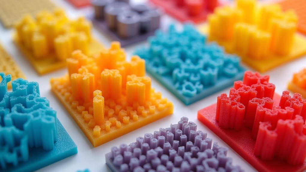
You’ll maximize your 3D print strength by using high-density modifiers at stress points with 100% infill, honeycomb patterns for weight balance at 15-30% density, and cubic subdivision for complex geometries. Apply concentric rings for curved surfaces, grid patterns for multi-directional forces, and triangular infill for shear resistance. Lightning patterns optimize speed at 10-15% density, while cross patterns work best for flexible joints. Custom density gradients let you vary reinforcement across different zones. These targeted approaches will transform your printing results when properly implemented.
High-Density Reinforcement Modifiers for Critical Load-Bearing Zones
When you’re designing functional prints that must withstand significant stress, high-density reinforcement modifiers become essential tools for targeting critical load-bearing zones without unnecessarily increasing your part’s overall weight.
You’ll want to strategically place these modifiers at joints and attachment points where maximum structural integrity matters most. Set these critical areas to 100% infill density to dramatically improve resistance against crushing forces.
Choose concentric infill patterns for your high-density reinforcement modifiers since they distribute strength uniformly around modified zones, making them perfect for cylindrical structures.
Increase wall layers alongside your modifiers for enhanced durability and robust external support.
Design your modifier meshes carefully in CAD software to achieve targeted reinforcement while maintaining efficient material usage and ideal print performance.
Honeycomb Pattern Modifiers for Optimal Strength-to-Weight Balance
When you need maximum strength without the weight penalty, honeycomb pattern modifiers deliver the perfect engineering solution for your 3D prints.
You’ll find that the hexagonal geometry naturally distributes loads across the structure while using considerably less material than solid infill alternatives.
The key lies in understanding how to implement these patterns effectively and adjusting density settings to match your specific application requirements.
Honeycomb Structural Advantages
Among 3D printing’s most celebrated infill patterns, honeycomb stands out as the gold standard for achieving ideal strength-to-weight ratios in your prints.
This honeycomb infill efficiently distributes stress across its geometric structure, delivering superior resistance to deformation compared to conventional patterns.
You’ll find that honeycomb’s design optimizes material usage while reducing both print time and filament consumption.
The pattern’s strategic geometry maintains structural integrity in critical areas without adding unnecessary weight to your model.
When you apply honeycomb as an infill modifier, you can reinforce specific sections like joints or load-bearing zones.
You’ll also benefit from its customizable density and layer height options, letting you fine-tune the balance between strength and material savings to match your project’s exact requirements.
Implementation Best Practices
Understanding honeycomb’s structural benefits sets the foundation, but proper implementation determines whether you’ll achieve peak performance from these modifiers.
You’ll want to set your infill density between 15% to 30% for the ideal balance of strength and material efficiency. Pair honeycomb patterns with thicker outer walls and increased perimeter settings to maximize structural integrity without excessive weight gain.
Experiment with layer heights ranging from 0.1mm to 0.3mm depending on your priorities. Choose finer layers when detail matters most, or select coarser layers when you need faster print times.
This combination of proper infill density settings, wall thickness adjustments, and strategic layer height selection guarantees you’re extracting maximum value from honeycomb modifiers in your targeted print areas.
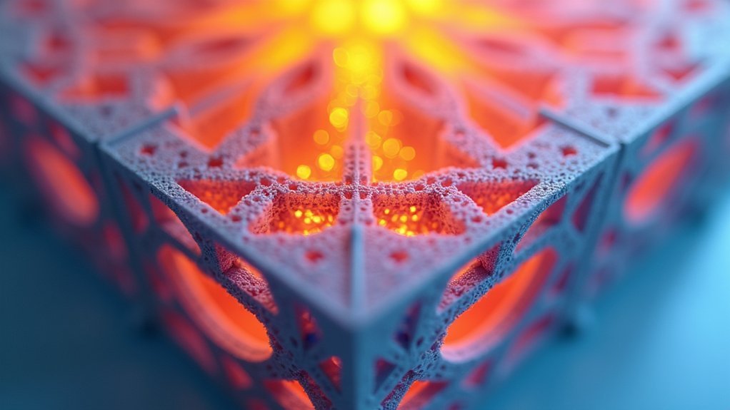
Cubic Subdivision Modifiers for Complex Geometric Reinforcement
As 3D printing projects grow increasingly complex, cubic subdivision modifiers offer a sophisticated approach to infill enhancement that balances structural integrity with material efficiency.
You’ll find this algorithm divides internal volumes into smaller cubic sections, providing multidirectional support without greatly extending print times. The pattern excels at 20-30% infill density, delivering superior performance for intricate geometric designs requiring strength-to-weight ratios.
You can strategically reinforce critical areas like joints or load-bearing sections while conserving material in less stressed regions. This selective approach maximizes resource efficiency without compromising durability.
Most slicer software supports cubic subdivision modifiers, enabling seamless integration into your existing workflows. You’ll appreciate the fine-tuning capabilities that let you customize settings for specific project requirements, making this infill pattern ideal for complex geometric reinforcement applications.
Concentric Ring Modifiers for Cylindrical and Curved Surfaces
When you’re printing cylindrical or curved objects, you’ll need to optimize your ring pattern spacing to match the object’s curvature and structural requirements.
Proper spacing guarantees each concentric ring distributes loads effectively while maintaining material efficiency throughout the print.
You must also master curved surface adhesion techniques that minimize layer separation and create seamless bonds between the infill rings and your object’s walls.
Optimal Ring Pattern Spacing
Three critical factors determine ideal ring pattern spacing for concentric infill modifiers: part geometry, load requirements, and material efficiency goals.
When you’re configuring efficient ring pattern spacing, you’ll need to balance structural strength with material conservation. Tighter spacing between rings provides enhanced support for load-bearing areas, making it perfect for functional parts requiring maximum durability. Conversely, wider spacing reduces material usage while maintaining adequate strength for lighter applications.
You should align ring widths and spacing with your part’s overall geometry to prevent weak points. This strategic approach guarantees uniform strength distribution throughout curved surfaces.
For most applications, you’ll find that adjusting spacing based on stress concentration areas delivers the best results, maximizing both performance and cost-effectiveness.
Curved Surface Adhesion Techniques
Cylindrical and curved surfaces present unique adhesion challenges that you’ll overcome by strategically implementing concentric ring modifiers.
These circular layers naturally conform to your object’s curvature, creating superior surface contact compared to traditional linear patterns. You’ll achieve stronger bonding while maintaining ideal weight distribution by adjusting concentric infill density specifically at curved areas.
This technique dramatically reduces delamination risks since the extruded material follows your object’s natural contours. You’ll notice fewer gaps and more uniform material distribution, resulting in higher overall print quality.
When you implement concentric modifiers correctly, you’ll achieve smoother surface finishes and enhanced aesthetics for cylindrical designs. The improved functionality and visual appeal make this approach essential for curved geometries requiring reliable adhesion performance.
Grid Pattern Modifiers for Multi-Directional Force Distribution
Since grid pattern modifiers create intersecting lines that distribute stress evenly across multiple axes, they’re ideal when you need your printed parts to handle forces coming from different directions.
You’ll find these modifiers particularly effective for functional prototypes and mechanical components that require shear resistance without excessive weight.
The beauty of grid pattern modifiers lies in their efficiency—you’ll achieve balanced material usage while maintaining structural integrity.
You can customize grid density from 15% to 50% infill depending on your strength requirements. This flexibility lets you optimize the strength-to-weight ratio for your specific application.
You’ll also appreciate the reduced print times compared to complex infill patterns, making grid modifiers an excellent choice when you need reliable performance without sacrificing speed or material efficiency.
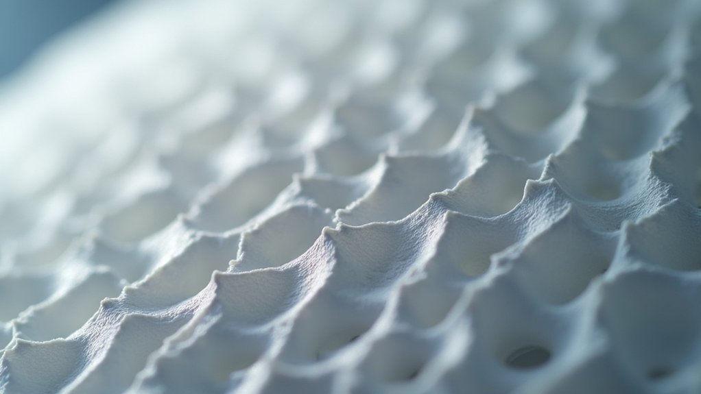
Gyroid Modifiers for Isotropic Strength Enhancement
When your printed parts need uniform strength in all directions, gyroid modifiers deliver exceptional isotropic performance through their continuous, wavy three-dimensional structure.
This gyroid infill pattern maximizes your strength-to-weight ratio by effectively distributing loads throughout the entire print, creating lightweight structures without sacrificing performance.
You’ll find gyroid modifiers particularly beneficial in areas experiencing dynamic loads or stress, as the continuous pattern absorbs and dissipates forces evenly.
Maintain moderate infill density around 20-30% to balance weight reduction with structural integrity efficiently.
The implementation reduces material usage by up to 30% compared to denser patterns, making it a cost-effective choice for producing strong yet lightweight components.
This makes gyroid infill ideal for functional parts requiring consistent durability across all directional forces.
Triangular Infill Modifiers for Shear-Resistant Applications
Triangular infill modifiers excel in applications where shear resistance takes priority over isotropic strength distribution.
You’ll find this geometric pattern distributes forces evenly across your print, making it ideal for functional parts that experience multi-directional stress.
When implementing triangular infill modifiers, consider these key factors:
- Density requirements – Use 20-50% infill density depending on your load specifications.
- Application suitability – Perfect for brackets, supports, and structural components.
- Material efficiency – Achieves superior strength-to-weight ratios for lightweight designs.
- Dynamic performance – Enhances durability in environments with impact loads or vibrations.
You’ll achieve superior structural integrity while maintaining material efficiency, particularly when your parts need to withstand complex force patterns rather than uniform loading conditions.
Lightning Pattern Modifiers for Rapid Print Speed Optimization
While triangular patterns prioritize strength, Lightning pattern modifiers revolutionize your printing workflow by dramatically reducing print times without compromising essential structural requirements.
You’ll achieve peak speed by implementing lightning pattern modifiers at 10-15% density, creating lightweight structures that minimize material consumption. The zigzagging design eliminates excessive travel moves, allowing your print head to work more efficiently across each layer.
You can strategically apply these modifiers to non-critical sections while maintaining denser patterns in stress-bearing areas. This targeted approach lets you balance rapid production with functional integrity.
Lightning pattern modifiers excel for prototypes and non-functional models where speed takes precedence. By combining these modifiers with reinforcement patterns in critical zones, you’ll maximize printing efficiency while preserving structural performance where it matters most.
Cross Pattern Modifiers for Flexible Joint Areas
When you need flexible joints in your 3D prints, cross pattern modifiers offer a strategic solution that balances movement capability with structural integrity.
You’ll find that cross patterns minimize long continuous lines that create weak points, instead distributing loads through intersecting geometry that flexes without breaking.
This approach lets you optimize joint flexibility while maintaining enough strength for repeated movement in applications like robotic components or wearable devices.
Cross Pattern Mechanics
Many 3D printing applications require joints that can flex without breaking, and the Cross pattern infill delivers this capability through its unique interconnected line structure.
During infill generation, the pattern creates a mesh of crossing lines that distribute mechanical stress evenly throughout your print. This strategic force distribution prevents concentrated stress points that typically cause joint failures.
The Cross pattern’s mechanical advantages include:
- Even force distribution – Interconnected lines spread loads across multiple contact points
- Minimal weak spots – Short segmented lines eliminate long straight vulnerabilities
- Low-density efficiency – Maintains strength at reduced infill percentages for lighter prints
- Flexible resilience – Allows controlled movement while preserving structural integrity
You’ll find this pattern excels in applications requiring repeated flexing motions, where traditional infill patterns would crack or fail under cyclic loading conditions.
Joint Flexibility Optimization
Cross pattern modifiers take these mechanical advantages a step further by allowing you to target specific joint areas where flexibility matters most.
You’ll find this infill pattern particularly valuable for robotics and wearable devices where smooth articulation is essential. The interconnected lines reduce rigidity while maintaining structural integrity, letting your joints bend without breaking under stress.
You can run lower infill densities in these critical areas, conserving material while ensuring adequate support for dynamic movements.
The cross pattern distributes stress more evenly across joint surfaces, preventing the localized failures common with solid infill approaches.
When you implement these modifiers strategically, you’ll considerably improve both performance and longevity of parts experiencing repetitive motion, creating more durable and functional printed components.
Custom Density Gradient Modifiers for Variable Stress Regions
How can you guarantee your 3D prints maintain strength where it’s needed most while avoiding unnecessary material waste?
Custom density gradient modifiers let you adjust infill density locally within your print, creating targeted reinforcement in stress-critical areas like joints and load-bearing sections.
You’ll shift seamlessly from high-density infill in critical zones to lower-density regions where less support’s required. This approach optimizes material use while preserving structural integrity, reducing both weight and costs without compromising performance.
Here’s how to implement custom density gradient modifiers effectively:
- Create gradient modifiers using CAD software like Fusion 360
- Import modifiers into your slicing software for customization
- Combine experimental patterns like Gyroid with density gradients
- Target specific regions based on anticipated stress distribution
Frequently Asked Questions
What Is the Best Infill for Printing Terrain?
You’ll want grid or honeycomb infill at 10-15% density for most terrain printing. For detailed areas like peaks, use modifiers to increase density to 30-40% while keeping overall weight low.
What Infill Percentage Settings Work Best for Most Prints?
You’ll want to use 15-30% infill for most prints, as it balances strength with material efficiency. You can go lower at 10-15% for decorative items or higher at 50%+ for functional parts.
Is 40% Infill Too Much?
It depends on your print’s purpose. You’ll waste time and material if it’s decorative, but you’ll need 40% for functional parts requiring strength. Most prints work fine with 15-30% infill.
What Is the Best Infill Pattern for Aesthetics?
You’ll find honeycomb infill works best for aesthetic prints since it creates visually appealing patterns while using material efficiently. Triangular patterns also provide unique textures that enhance decorative items’ appearance beautifully.

Leave a Reply