You’ll want to use 10-20% infill density for prototypes since they’re focused on testing form and fit rather than strength, keeping costs low and print times manageable. For production parts, you’ll need at least 50% infill density to meet mechanical requirements, with high-stress applications requiring 75% or higher for adequate tensile strength. This dramatic difference reflects the trade-off between quick, economical testing versus durable end-use functionality. Understanding these density ranges and their corresponding infill patterns will help you optimize both performance and manufacturing efficiency.
Understanding Infill Density in FDM 3D Printing
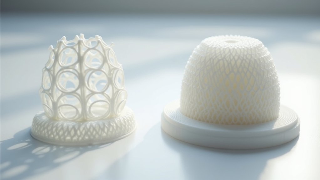
When you’re diving into FDM 3D printing, infill density becomes one of your most important decisions, controlling the internal structure of your prints and ranging from 0% for completely hollow objects to 100% for solid parts.
This setting directly impacts three vital factors: strength, weight, and print time.
Your choice of infill density dramatically affects structural integrity. Higher densities provide greater strength – a part with 50% infill is approximately 25% stronger than one with 25% infill.
However, increased density means more material usage, higher costs, and longer print times.
Understanding this balance is essential when deciding between prototypes and production parts. Prototypes focus on visual testing, while production parts must withstand mechanical stress, requiring different infill strategies.
Key Differences Between Prototype and Production Parts
The fundamental distinction between prototype and production parts lies in their intended purpose and performance requirements.
Understanding whether you’re building for testing or real-world deployment fundamentally changes your manufacturing approach and quality standards.
When you’re creating prototypes, you’ll typically use infill percentages between 0% and 15% since you’re focused on testing form and fit rather than strength. This low infill density dramatically reduces print times and material costs, allowing you to iterate quickly through design changes.
However, production parts demand much higher standards.
You’ll need minimum infill percentages of 50% to guarantee adequate mechanical properties for real-world use. These parts often require infill densities up to 100% depending on their application. While this increases manufacturing time and costs, it’s crucial for achieving the durability and performance characteristics your end-users expect from production parts.
Optimal Infill Density Ranges for Prototypes

Since prototype requirements vary considerably based on their intended use, you’ll need to select infill densities that match your specific testing goals.
For visual prototypes focused on concept validation, you’ll find 10% to 15% infill density provides adequate structural integrity while minimizing material costs and print time. These lower densities work perfectly when aesthetics matter more than strength.
However, if you’re creating functional prototypes that require mechanical testing, you should increase infill density to 20% to 30%. This range guarantees your prototypes can withstand stress testing while maintaining reasonable production speeds.
Choose efficient infill patterns like grid or lines to optimize both strength and print time. Remember, the prototype’s specific application determines your exact infill percentage—prioritize lower densities for aesthetic models and higher densities for functional validation.
Recommended Infill Density for Production Parts
When you’re designing production parts, you’ll need considerably higher infill densities than prototypes to meet demanding mechanical property requirements.
High stress applications require infill densities of at least 50% to handle the loads and forces your parts will face in real-world use.
You can’t compromise on structural integrity when components must perform reliably under constant mechanical stress and repeated loading cycles.
High Stress Applications
Manufacturing production parts that’ll endure high-stress environments requires infill densities of at least 50% to guarantee adequate strength and durability under mechanical loads.
You’ll want to increase infill density to around 75% or higher for high-stress applications, as this greatly improves tensile strength and makes your parts more resilient to deformation and failure.
Choose infill patterns like cubic infill or gyroid, which provide balanced strength in all directions.
You can optimize part performance further by implementing variable density strategies that adjust based on specific load areas, enhancing strength while conserving material.
Remember to conduct regular testing and mechanical analysis to guide your density selection, as higher densities increase weight and printing time but deliver stronger end products.
Mechanical Property Requirements
Beyond stress considerations, you’ll need to match infill density to your part’s specific mechanical property requirements for optimal production performance.
For production parts requiring mechanical strength, you should use a minimum infill density of 50% to guarantee adequate durability. This percentage provides an ideal balance between strength and weight for most applications.
When creating functional parts that’ll undergo significant loads, you’ll want a higher infill percentage ranging from 70% to 100% for maximum stability.
For components requiring drilling or fastening, maintain at least 50% density to assure sufficient screw retention and structural integrity.
Consider utilizing advanced infill patterns like cubic or gyroid at elevated densities. These patterns enhance mechanical properties while keeping your parts lighter than solid infill structures.
How Infill Density Affects Part Strength and Weight
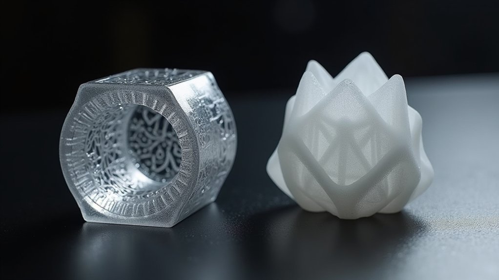
When you increase infill density, you’re making a direct trade-off between part strength and weight that’ll impact your project’s performance.
You’ll see roughly 25% strength gains for every 25% density increase, but this comes with proportional weight penalties that can compromise applications where mass matters.
Testing your specific mechanical requirements against these density-weight relationships helps you find the sweet spot between structural integrity and practical usability.
Density-Strength Relationship Analysis
Understanding how infill density directly impacts your part’s mechanical properties is vital for making informed decisions between prototype and production settings. The density-strength relationship follows a clear pattern: increasing infill density from 25% to 50% delivers approximately 25% stronger parts, making this jump essential for functional parts requiring durability.
For prototypes focused on visual verification, you’ll typically use 20% infill to minimize material costs while achieving adequate form representation. However, production parts demanding mechanical integrity require 50% or higher infill density to withstand operational stress.
You’ll need to balance strength requirements against weight penalties, as higher densities considerably increase your part’s mass. This trade-off becomes vital when designing weight-sensitive applications where structural performance must justify the added material investment.
Weight Trade-off Considerations
As you increase infill density, you’ll face a critical trade-off between enhanced structural performance and unwanted weight gain that can compromise your part’s functionality.
Understanding this weight trade-off helps you optimize your designs for specific applications while managing material costs effectively.
Consider these density guidelines for different applications:
- Lightweight prototypes (0-15% infill) – Minimize weight and material costs while maintaining basic structural integrity for testing concepts.
- Functional parts (25-50% infill) – Balance durability with reasonable weight for production parts requiring moderate strength.
- Maximum strength applications (100% infill) – Accept significant weight increase for critical structural integrity when performance outweighs weight concerns.
Your infill density choice should align with whether you’re creating a prototype for validation or production parts requiring long-term durability.
Mechanical Performance Testing
Testing your parts under real-world conditions reveals how infill density directly impacts both strength and weight performance.
When you’re conducting mechanical performance evaluations, you’ll find that production parts with 50% minimum infill density deliver considerably enhanced tensile strength compared to prototype testing standards of 10-20%. Higher densities of 75-100% can boost your part’s strength by up to 25%, making them ideal for stress-bearing applications.
Your infill pattern choice matters equally. Cubic or gyroid patterns provide superior isotropic strength compared to basic line patterns, especially at higher densities.
During prototype testing, you might accept some deformation under load, but production parts demand consistent strength and durability. Lower infill densities often result in insufficient rigidity, emphasizing why mechanical testing helps determine ideal density for your specific application requirements.
Material Cost Considerations for Different Infill Densities
When you’re selecting infill density for your 3D printing projects, material costs become a primary factor that directly impacts your budget and project viability.
Different infill densities create substantial cost variations that you’ll need to balance against performance requirements.
Consider these cost-effective infill density strategies:
- Prototypes: Use 0-15% infill density to minimize material costs while enabling rapid design validation and iteration.
- Functional parts: Apply minimum 50% infill density to guarantee adequate strength, accepting higher production expenses for durability.
- Critical components: Implement 100% infill for maximum strength when performance outweighs cost concerns.
You can achieve significant savings by adjusting your ideal infill percentage based on each part’s intended use.
The default 20% infill provides balanced cost-performance for standard applications, but strategic density selection maximizes your material budget efficiency.
Print Time Impact of Varying Infill Percentages
You’ll notice that print times increase in a nearly linear fashion as you raise infill percentages, with each 10% jump adding roughly 15-20% more printing time to your project.
This predictable relationship means you can accurately estimate how much longer your production parts will take compared to your initial prototypes.
Understanding this time impact lets you implement smart efficiency strategies that balance your quality requirements against project deadlines and production schedules.
Linear Time Increase
As infill density increases, print times climb at a predictable rate that directly impacts your project timeline.
Understanding this linear relationship helps you make informed decisions when balancing speed against strength requirements for prototypes versus production runs.
The mathematical progression follows consistent patterns:
- Every 10% infill increase adds 10-20 minutes to your overall print time, regardless of whether you’re printing prototypes or production parts.
- Higher infill density beyond 50% doubles manufacturing time compared to lighter internal structure configurations.
- Maximum density settings (75-100%) extend print time by 200-300% over standard prototype specifications.
This predictable scaling means you can accurately estimate production schedules by calculating the time penalty for each infill percentage increase, ensuring realistic project delivery expectations.
Efficiency Optimization Strategies
Knowing these time penalties empowers you to implement targeted strategies that maximize efficiency without compromising your project goals.
You can enhance infill density by choosing advanced patterns like honeycomb or gyroid, which deliver superior strength-to-weight ratios while maintaining reasonable print time compared to solid fills.
Variable infill offers the most strategic approach—you’ll apply lower densities in non-critical areas and higher densities where structural integrity matters most. This technique reduces overall material usage without sacrificing performance in production parts.
For prototypes, stick to 0-15% infill to minimize both time and costs.
When manufacturing functional components, strategically balance your infill density requirements against acceptable print time increases to achieve peak efficiency.
Best Infill Patterns for Prototype Applications
Prototyping demands speed and efficiency over maximum strength, making your choice of infill pattern essential for balancing print time with adequate structural performance.
When selecting from the various infill patterns available for prototypes, you’ll want to prioritize rapid printing while maintaining sufficient structural integrity for visual assessments and basic functionality testing.
The most effective patterns for prototype applications include:
- Grid and Lines – Provide moderate strength with fast print speeds, perfect for quick iterations when you’re using minimal infill density.
- Triangular Pattern – Delivers enhanced structural integrity without dramatically increasing material use or print time.
- Honeycomb – Balances strength and weight efficiently, creating robust internal structures while optimizing material consumption for prototypes requiring slightly more durability.
Selecting Infill Patterns for Production-Grade Parts
When shifting from prototypes to production-grade parts, you’ll need infill patterns that prioritize structural integrity and long-term durability over print speed.
For production applications, maintain an infill density of at least 50% to guarantee adequate mechanical properties under stress.
The cubic infill pattern stands out for its balanced strength distribution across all directions, making it ideal for functional components.
Honeycomb patterns excel when you need a superior strength-to-weight ratio while minimizing material consumption.
Gyroid and octet patterns work exceptionally well in high-stress areas where load distribution demands exceptional performance.
Always align your infill choice with the specific mechanical requirements of your end-use application, considering factors like strength, flexibility, and weight constraints.
Balancing Performance Requirements With Manufacturing Efficiency
Finding the sweet spot between performance demands and manufacturing efficiency requires a strategic approach to infill density that differs greatly between prototyping and production phases.
Strategic infill density optimization balances performance requirements with manufacturing efficiency across different production phases.
For prototypes, you’ll want to prioritize speed and material usage efficiency by setting infill density between 10-20%. This allows rapid iteration testing while minimizing costs and print time.
Production parts demand higher infill density of 50% or more to meet stringent performance requirements for real-world applications.
Strategic considerations for optimizing manufacturing efficiency include:
- Prototype Phase: Use minimal infill to accelerate design iterations and reduce material waste
- Production Phase: Implement higher infill densities to guarantee mechanical strength and durability
- Cost Analysis: Balance material usage against performance specifications to maximize manufacturing efficiency
This approach optimizes both development speed and final product quality.
Frequently Asked Questions
What Is the Best Infill for Prototypes?
You’ll want 10-20% infill density for most prototypes, using grid or lines patterns. This balances material savings with adequate strength for visual testing while keeping costs low and print times fast.
Is 20% Infill Strong Enough?
You’ll find 20% infill adequate for visual prototypes and basic testing, but it won’t handle high stress well. For functional prototypes requiring mechanical testing, you’ll need at least 50% infill density.
Is 40% Infill Too Much?
You’ll find 40% infill excessive for most prototypes since it increases print time and material costs unnecessarily. However, it’s appropriate for production parts requiring high strength and durability in functional applications.
Is 25% Infill Strong?
You’ll find 25% infill provides moderate strength that’s suitable for prototypes and visual models, but it’s typically 10-20% weaker than higher densities and won’t handle significant mechanical stress well.


Leave a Reply