You can compare honeycomb vs grid infill strength by conducting standardized tensile tests using protocols like ASTM D638. Honeycomb’s hexagonal structure distributes loads more evenly across multiple directions, while grid infill concentrates stress at line intersections. Honeycomb consistently demonstrates superior tensile strength and layer adhesion due to its interconnected design, though it requires more complex printing paths. Grid excels in vertical applications but struggles with lateral forces. Understanding these testing methods will help you make informed decisions for your specific project needs.
Understanding Honeycomb Infill Pattern Structure
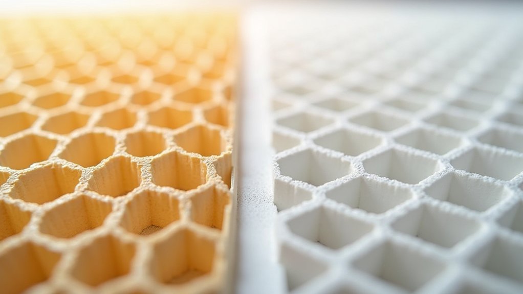
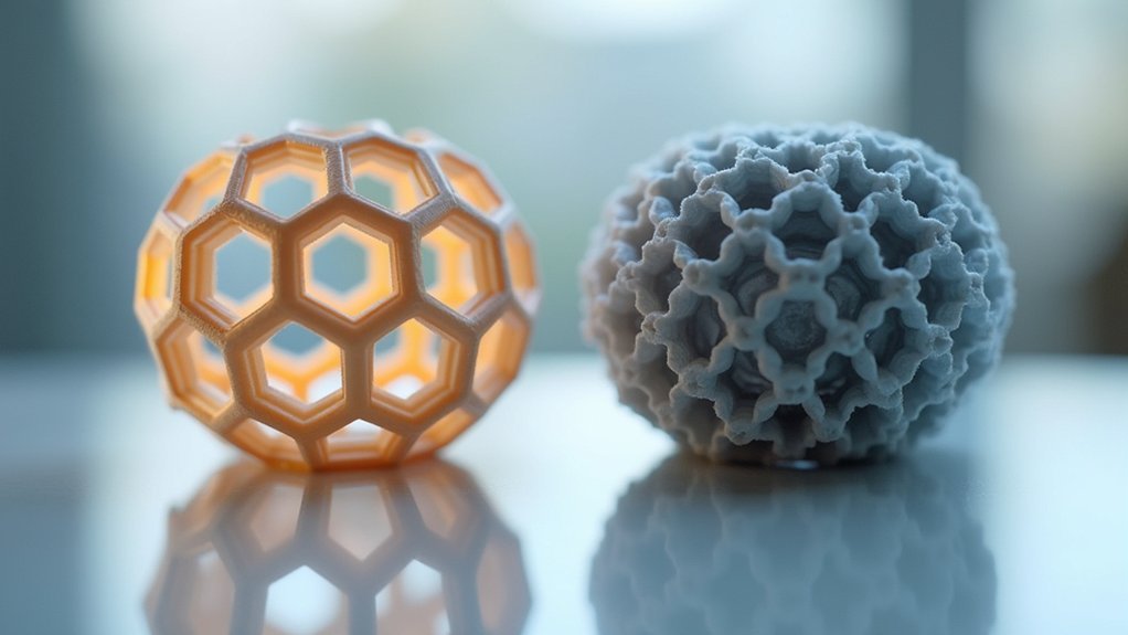
When you examine the honeycomb infill pattern under magnification, you’ll notice its distinctive hexagonal cell structure that mimics nature’s most efficient geometric design. This interconnected network of six-sided cells creates exceptional structural integrity by distributing forces evenly across multiple load paths.
Unlike simpler patterns, honeycomb infill optimizes load distribution through its sophisticated geometry, where each hexagon shares walls with neighboring cells, creating a unified support system.
Honeycomb’s interconnected hexagonal cells share structural walls, creating a unified support network that distributes loads more effectively than basic infill patterns.
You’ll find that this pattern requires more material than basic alternatives, but it delivers superior strength-to-weight ratios. The hexagonal structure excels when your printed parts face directional stresses, as the interconnected cells resist bending and deformation effectively.
This makes honeycomb infill particularly valuable for functional parts requiring both lightweight properties and robust mechanical performance.
Grid Infill Pattern Mechanics and Design
Two perpendicular sets of straight lines form the foundation of grid infill pattern mechanics, creating a simple yet effective internal structure that prioritizes vertical strength and manufacturing efficiency.
You’ll find this grid infill pattern excels in applications requiring robust vertical support due to its perpendicular line arrangement. The straightforward design enables faster printing since your printer’s nozzle follows less complex routing compared to intricate 3D patterns.
However, you’ll encounter some trade-offs with mechanical performance. While the pattern delivers moderate strength for standard applications, it doesn’t distribute loads as evenly as advanced alternatives like honeycomb or gyroid.
Additionally, material usage becomes less efficient because overlapping lines often create redundancy. You’ll need to balance these factors when choosing grid infill for your specific project requirements.
Tensile Strength Testing Methods for Infill Patterns
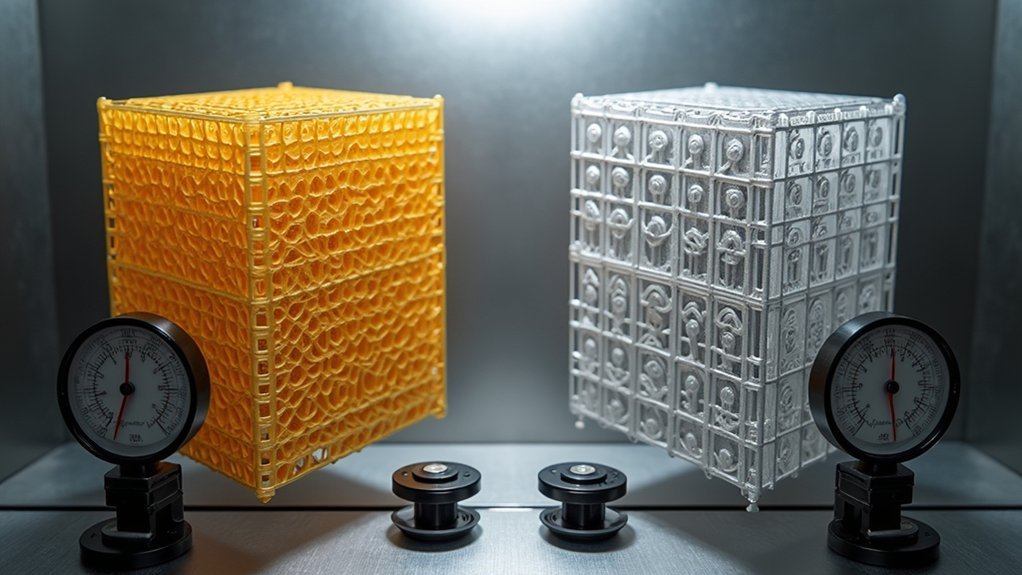
When you’re testing infill strength, you’ll need to follow standardized protocols like ASTM D638 to guarantee your results are reliable and comparable across different patterns.
You’ll apply uniaxial forces systematically to your test samples, gradually increasing the load until failure occurs.
Your data collection must capture peak strength values, failure modes, and stress distribution patterns to accurately compare how honeycomb and grid infills perform under tension.
Standard Testing Protocols
Although 3D printing offers countless design possibilities, you’ll need standardized testing protocols to accurately compare the tensile strength of different infill patterns. ASTM D638 for plastics provides the framework for creating dog-bone samples that guarantee consistent evaluation between honeycomb and grid configurations.
When preparing your test specimens, you must control critical parameters including infill density, layer adhesion, and print orientation. These variables directly impact your results and can skew comparisons if not properly managed.
The protocol requires measuring maximum load capacity before sample failure, giving you direct performance data.
You’ll find that honeycomb infill consistently demonstrates higher peak strength values than grid patterns during testing. However, your material choice greatly influences outcomes, as different filaments exhibit distinct performance characteristics when combined with specific infill geometries.
Load Application Methods
Testing infill strength requires precise load application methods that guarantee accurate measurement of material performance under stress.
You’ll need to apply uniaxial loads gradually and consistently when evaluating tensile strength across different infill patterns. Your testing equipment should maintain steady force application rates to ascertain reliable data collection throughout the stress-strain process.
When comparing honeycomb versus grid configurations, you must use identical load application methods for both samples.
Position your specimens securely in testing grips to prevent slippage during force application. The load should increase at predetermined rates until material failure occurs, allowing you to capture ultimate tensile strength values accurately.
These standardized load application methods ascertain your comparative analysis between infill patterns produces meaningful, reproducible results for engineering decisions.
Data Collection Techniques
Your load application methods work hand-in-hand with systematic data collection techniques that capture the complete mechanical behavior of honeycomb and grid infill patterns.
You’ll need to record ultimate tensile strength (UTS), yield strength, and elongation at break for each specimen during testing. Your universal testing machine should continuously log force and displacement data throughout the entire loading cycle until failure occurs.
Document environmental conditions including temperature and humidity, as these factors directly influence your results.
You’ll want to test multiple specimens of each infill pattern to guarantee statistical validity. Record both tensile strength and compressive strength values when applicable, noting any variations between honeycomb and grid performances.
Maintain consistent data collection protocols across all tests to enable accurate comparisons between infill patterns.
Load Distribution Analysis in Honeycomb Vs Grid
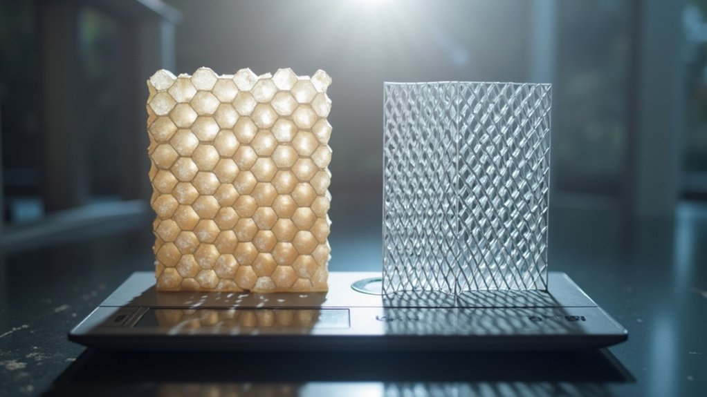
When analyzing how different infill patterns handle mechanical stress, you’ll find that honeycomb and grid structures distribute loads through fundamentally different mechanisms. Honeycomb infill spreads forces evenly across its hexagonal cells, eliminating stress concentration points that commonly appear in grid infill’s linear crossings. This geometric advantage gives honeycomb superior performance under multi-directional loads.
| Aspect | Honeycomb | Grid |
|---|---|---|
| Stress Distribution | Even across hexagonal structure | Concentrated at line intersections |
| Load Direction | Multi-directional resistance | Primarily unidirectional |
| Failure Points | Minimized weak spots | Vulnerable crossing lines |
Grid infill’s perpendicular lines create predictable failure paths where shear forces accumulate. You’ll notice honeycomb’s cellular structure better handles compression and impact forces, absorbing energy throughout the entire pattern rather than channeling stress into specific weak points.
Material Efficiency Comparison Between Patterns
When you’re choosing between honeycomb and grid infill patterns, you’ll find that material efficiency becomes an essential factor in your printing decisions.
Honeycomb infill uses approximately 30% less filament than grid infill while maintaining comparable strength, thanks to its optimized geometric design that eliminates redundant material placement.
You’ll also notice faster print times with honeycomb patterns since they require fewer tool path movements and less extrusion time compared to grid’s overlapping line structure.
Material Usage Per Pattern
When you’re printing with grid patterns, you’re using simple straight lines in two directions, making it more material-efficient.
This efficiency becomes particularly noticeable at lower infill densities where honeycomb’s complex design demands more filament.
If you’re prioritizing cost-effectiveness over maximum strength, grid infill offers faster print times and reduced filament waste.
You’ll save money on materials while maintaining adequate structural integrity for less demanding applications.
Print Time Efficiency
Although honeycomb infill delivers superior strength, it’ll markedly slow down your printing process compared to grid patterns.
Grid infill utilizes straight lines in two directions, making it considerably faster for quick prints that don’t require maximum structural integrity. The complex geometry of honeycomb infill increases both slicing times and layer computations, adding considerable overhead to your workflow.
Key factors affecting print times include:
- Grid patterns reduce overall printing duration, especially in larger models
- Honeycomb’s intricate structure requires more processing power during slicing
- Straight-line movements in grid infill allow faster print head acceleration
- Complex layer computations make honeycomb less efficient for time-sensitive projects
You’ll find grid infill particularly beneficial when speed matters more than ultimate strength.
Print Speed and Time Considerations
Beyond strength considerations, you’ll find that print speed and time requirements differ markedly between honeycomb and grid infill patterns.
Grid infill’s straightforward design with perpendicular lines enables faster print speed since your printer follows simpler toolpaths. You can optimize grid patterns by adjusting infill density percentages, achieving quicker prints while maintaining adequate structural integrity.
Honeycomb infill demands more time due to its complex geometric structure requiring additional material and processing power. The intricate hexagonal pattern extends slicing times and layer processing duration.
You’ll often need higher infill density with honeycomb to reach desired strength levels, further increasing print duration. While honeycomb provides superior support for specific applications, grid infill consistently delivers faster results when time efficiency matters most for your projects.
Layer Adhesion Performance in Different Patterns
While print speed matters for project efficiency, layer adhesion performance fundamentally determines your print’s structural reliability and long-term durability.
When you’re choosing between honeycomb infill and grid infill, you’ll notice significant differences in how layers bond together.
Honeycomb infill consistently outperforms grid infill in layer adhesion due to its interconnected structure that distributes stresses across multiple directions.
Grid infill’s linear crossing patterns create weak points where layers struggle to bond effectively, making your prints more vulnerable to failure.
- Honeycomb’s multi-directional geometry enhances bonding between layers compared to grid’s linear structure
- Grid infill suffers from crossing line intersections that create adhesion weak points
- Honeycomb distributes loads effectively, maintaining structural integrity during dynamic stress
- Studies show honeycomb infill produces higher tensile strength values in durability applications
Directional Strength Properties and Limitations
When you examine directional strength properties, honeycomb infill’s triangular geometry creates superior load distribution across multiple axes compared to grid infill’s two-directional linear structure.
You’ll find honeycomb maintains consistent strength regardless of load direction, making it ideal for complex stress applications.
Grid infill shows excellent vertical performance but struggles with shear and lateral forces due to crossing line intersections that create failure points.
Grid infill excels vertically but fails under shear forces where crossing lines create structural weak points.
Honeycomb’s design lets you achieve reliable strength even at lower densities, while grid patterns need higher densities for comparable performance.
However, you’ll face trade-offs with honeycomb requiring more material and longer print times.
Grid infill compromises strength when loads aren’t aligned with its linear structure, limiting its versatility in multi-directional stress scenarios.
Real-World Testing Scenarios and Applications
Laboratory testing scenarios reveal honeycomb infill’s superior performance in real-world stress conditions.
When you’re choosing between honeycomb infill and grid infill for your projects, understanding their practical applications makes all the difference.
Tensile strength tests consistently demonstrate honeycomb’s advantage in peak strength and load distribution, making it your go-to choice for high-durability applications.
You’ll find honeycomb infill excels in functional prototypes where stress distribution is critical, while grid infill works well for general structural support.
Here’s what real-world testing shows:
- Honeycomb outperforms grid in tensile strength tests
- Superior stress distribution reduces failure likelihood under load
- Honeycomb handles directional loads better than grid patterns
- Grid infill remains adequate for visual or low-stress applications
Choose honeycomb when strength matters most.
Density Settings Impact on Pattern Performance
Although both honeycomb and grid infill patterns respond to density adjustments, they don’t react equally to these changes.
You’ll find that honeycomb infill maintains excellent structural integrity even at lower density settings, performing effectively around 15-25% infill percentage. This geometric efficiency means you can achieve strong prints without excessive material usage.
Grid infill requires different considerations for ideal performance. You’ll need higher density settings to match honeycomb’s strength, particularly when your prints face lateral loads.
While the standard 30-50% range works for both patterns, grid typically benefits from the higher end of this spectrum.
Testing various density settings helps you enhance each pattern’s performance. The strength of printed parts depends heavily on matching the right infill percentage to your specific pattern choice and application requirements.
Slicer Software Settings for Optimal Results
Proper slicer configuration transforms your understanding of density settings into actual print performance.
Your slicing software choices directly impact how honeycomb and grid patterns translate into real-world strength.
Set infill density between 30-50% in Cura or similar software to achieve peak strength-to-weight ratios for functional prints.
Optimize functional prints by setting infill density to 30-50% for maximum strength-to-weight performance in your slicer software.
Advanced settings reveal additional performance improvements – increase wall count and outer shell thickness to enhance structural integrity regardless of your chosen pattern.
Key slicer optimizations include:
- Align infill line direction with primary stress directions for maximum load distribution
- Reduce layer height to improve adhesion and overall structural integrity
- Experiment with Gyroid or Cubic infill patterns for superior strength performance
- Utilize thicker outer shells through advanced settings for enhanced durability
These configurations guarantee your prints perform as designed.
Choosing the Right Pattern for Your Project Requirements
When selecting between honeycomb and grid infill, you’ll need to evaluate your project’s specific load requirements and how much stress the part will endure during use.
Consider whether your component faces directional forces that demand honeycomb’s superior load distribution, or if grid’s moderate strength suffices for less demanding applications.
You should also weigh material usage efficiency against performance needs, as honeycomb consumes more filament but delivers remarkably higher tensile strength.
Project Load Requirements
Three critical factors determine whether honeycomb or grid infill will best serve your project load requirements: the magnitude of forces involved, the direction of applied stress, and the duration of load exposure.
When you’re dealing with high-stress applications, honeycomb consistently outperforms grid infill in tensile strength tests through superior load distribution.
Grid infill struggles particularly when multi-directional forces come into play, while honeycomb handles complex stress patterns effectively.
Consider these key factors when evaluating your project’s needs:
- Peak force magnitude – High-stress applications demand honeycomb’s superior strength characteristics
- Load direction complexity – Multi-directional forces favor honeycomb’s efficient stress distribution
- Component criticality – Mechanical parts like brackets and gears require honeycomb’s enhanced durability
- Safety margins – Projects requiring maximum reliability benefit from honeycomb’s proven performance advantages
Material Usage Efficiency
Beyond meeting your project’s strength requirements, material usage efficiency plays a decisive role in determining which infill pattern delivers the best value for your specific application.
Honeycomb infill excels in this regard due to its exceptional strength-to-weight ratio, allowing you to use considerably less filament while maintaining structural integrity. You’ll typically achieve ideal results with honeycomb at 15-25% infill density, whereas grid patterns often require higher percentages for comparable strength.
The hexagonal structure’s superior load distribution means you’re not wasting material on unnecessary overlapping lines like grid infill creates.
This efficiency translates directly to cost savings, especially for functional prints where strength matters most. When material costs and print time are considerations, honeycomb consistently outperforms grid infill in overall efficiency.
Frequently Asked Questions
Is Honeycomb Infill the Strongest?
You’ll find honeycomb infill performs exceptionally well in strength tests, often outperforming other patterns like grid and triangle. However, it’s not universally strongest since effectiveness depends on your specific application, material, and print orientation.
How Do You Compare Infill Percentage to Strength?
You’ll find strength increases with higher infill percentages, but it’s not linear. Test different percentages between 15-40% to find your ideal balance of strength, material usage, and print time for each specific application.
What Is the Difference Between Grid and Hexagon Infill?
You’ll find grid infill uses intersecting lines in square patterns for moderate strength, while hexagon infill creates honeycomb structures that distribute stress better, offering superior tensile strength and material efficiency.
Is Cubic Infill Better Than Grid?
You’ll find cubic infill outperforms grid infill in strength tests due to its three-dimensional structure. It distributes loads better across multiple directions, preventing failures that grid’s two-dimensional pattern can’t handle effectively.

Leave a Reply