You’ll need precision measurements using photogrammetry techniques, capturing 20-30 burst photos from multiple angles with 60-80% overlap around your headlight mounting area. Use CAD software like SolidWorks or Fusion 360 to convert these photos into 3D models, then design your bracket with stress analysis testing. Print using ABS or PETG materials at 0.1-0.3mm layer heights, followed by careful post-processing including sanding and primer application for ideal fitment and durability that withstands real-world motorcycle operation stresses.
Understanding Headlight Bracket Requirements and Specifications
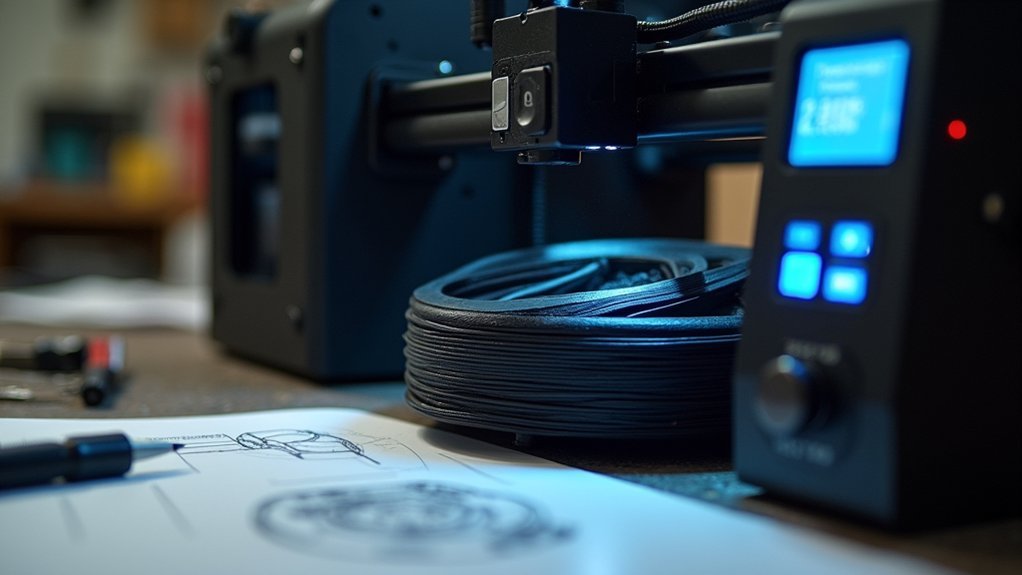
Precision forms the foundation of successful headlight bracket design, as even minor measurement errors can result in poor fitment and compromised safety.
Accurate measurements are absolutely critical – even small errors can lead to dangerous fitment issues and safety failures.
You’ll need to identify critical stress points where the bracket connects to your vehicle’s frame and where it supports the headlight assembly. Make sure you understand the pressure distribution across these mounting areas to prevent failure during operation.
Photogrammetry techniques will help you capture accurate 3D measurements of your headlight unit and existing mounting points. Input these measurements into CAD software to create a precise digital model.
Consider environmental factors like vibration, temperature fluctuations, and moisture exposure when establishing your specifications. Don’t forget integration requirements for additional components like speedometers or wiring harnesses that affect your bracket’s overall design parameters.
Essential Tools and Equipment for 3D Printing Brackets
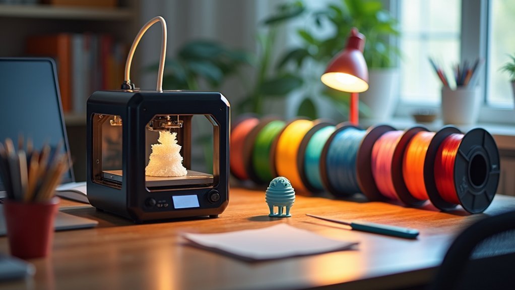
You’ll need the right 3D printer and CAD software to create functional headlight brackets that fit your motorcycle perfectly.
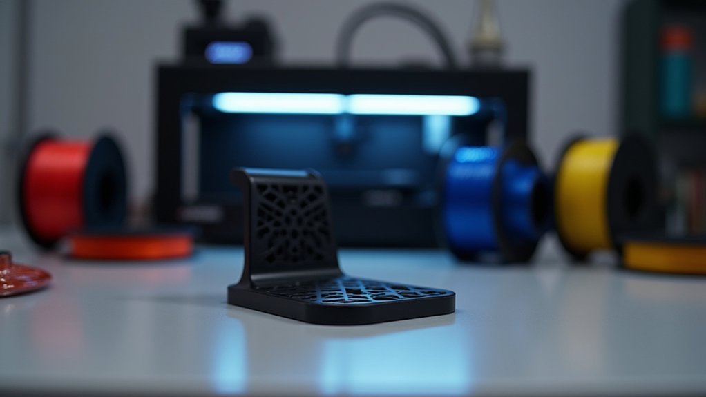
A high-quality FDM or SLA printer guarantees you can produce precise, durable brackets with the accuracy required for mounting critical components like headlights.
CAD software such as SolidWorks or Fusion 360 becomes essential for modeling your bracket’s exact dimensions and verifying compatibility with both your headlight unit and motorcycle’s structure.
3D Printer Selection
The foundation of successful headlight bracket printing starts with choosing the right 3D printer for your project’s demands.
You’ll need a machine that can handle automotive-grade requirements while delivering precision results.
Here’s what you should prioritize when selecting your printer:
- Build volume of at least 300mm x 300mm – Because your custom brackets deserve room to breathe and fit perfectly.
- Multi-filament compatibility (PLA, ABS, PETG) – So you can choose materials that won’t fail when temperatures rise.
- Heated bed capability – Because warped brackets mean wasted time and frustration.
- High resolution printing (0.1mm layer height minimum) – For those intricate details that make your brackets look professional.
Ensure your chosen printer works with advanced slicing software that optimizes complex geometries and support structures.
CAD Software Requirements
Once you’ve secured the right printer, creating accurate headlight brackets demands powerful CAD software that can handle automotive precision.
You’ll need programs like SolidWorks, AutoCAD, or Fusion 360 that provide extensive 3D modeling tools and stress simulation capabilities. These applications let you design brackets based on your photogrammetry measurements while analyzing pressure distribution and identifying potential failure points.
Your chosen software should support organic shape creation, allowing you to balance aesthetics with functionality.
Look for shape optimization features that’ll help you refine designs through iterative processes, strengthening weak areas while reducing unnecessary weight.
Integration capabilities are vital too—you’ll want to incorporate speedometers and other components within your model to guarantee seamless fitment before printing begins.
Photogrammetry Techniques for Accurate Measurements
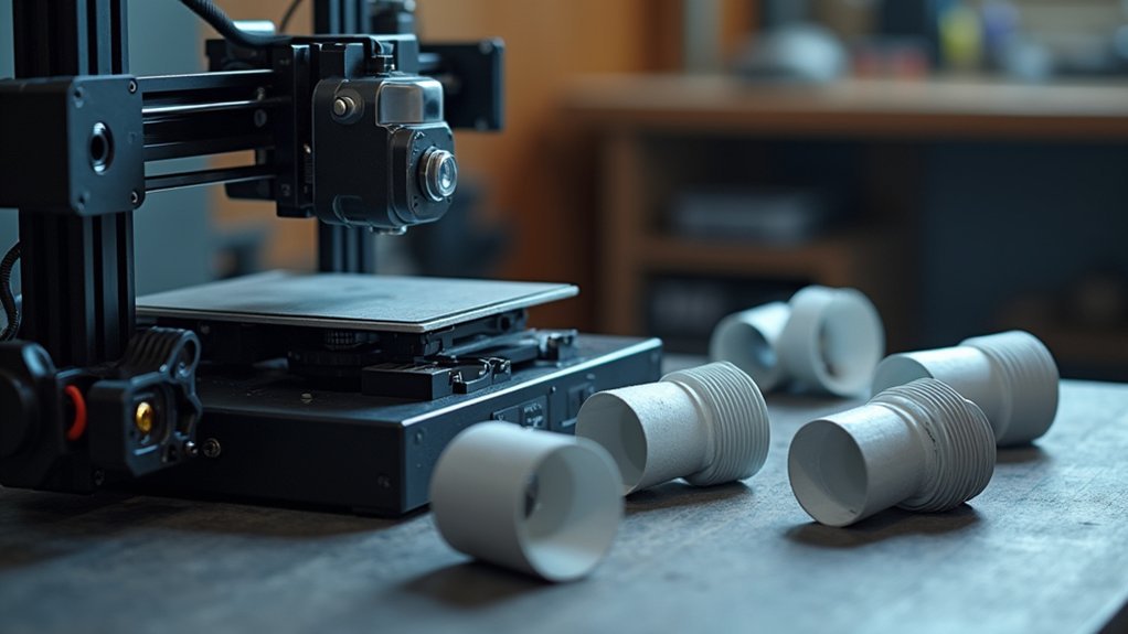
Precision becomes paramount when creating headlight brackets that must fit perfectly within your vehicle’s existing framework. Photogrammetry offers you a non-contact method to capture accurate measurements of complex mounting areas.
You’ll take burst photos from multiple angles around the headlight assembly, ensuring you’ve captured every contour and dimension. Process these images through specialized photogrammetry software to generate a detailed 3D model.
For ideal results, you’ll need good lighting and a clutter-free background during photo capture.
Here’s what makes photogrammetry invaluable for headlight brackets:
- Protects delicate components from potential damage during measurement
- Captures intricate curves that traditional measuring tools can’t reach
- Saves hours of manual measurement and sketching
- Delivers professional-grade accuracy for perfect fitment
Import your 3D model into CAD software for bracket design refinement.
Capturing Burst Photography for 3D Mapping
You’ll need to capture photos from at least 20-30 different angles around your headlight unit, ensuring each shot overlaps the previous one by 60-80% for ideal photogrammetry results.
Set your camera to burst mode and maintain consistent timing between shots—roughly 2-3 seconds per position—to avoid motion blur while moving around the object.
Position multiple LED panels or softboxes around your workspace to eliminate harsh shadows and create even illumination across all surfaces of the headlight assembly.
Photo Angle Requirements
The success of your 3D mapping depends heavily on capturing thorough burst photography from strategic angles around the headlight unit.
You’ll need systematic coverage to guarantee your photogrammetry software can reconstruct every detail accurately.
Here’s your essential angle strategy:
- Circle the headlight completely – Move 360 degrees around the unit, taking shots every 15-20 degrees to eliminate blind spots.
- Capture multiple elevation levels – Shoot from above, eye-level, and below to map complex curves and mounting points.
- Focus on critical mounting areas – Take extra close-up shots of bracket attachment points where precision matters most.
- Document hidden surfaces – Angle your camera to reveal recessed areas and undersides that standard shots miss.
Maintain consistent distance and overlap each image by 60-80% for ideal results.
Burst Sequence Timing
Once you’ve positioned yourself at each strategic angle, timing your burst sequences becomes the key to gathering enough data points for accurate reconstruction.
You’ll want to capture 20-30 burst photos from each position to provide your photogrammetry software with a thorough dataset. Set your camera to high shutter speed to eliminate motion blur and guarantee crisp detail capture from multiple perspectives.
Use a tripod to maintain consistent framing throughout each burst sequence, reducing variations that could compromise your 3D model’s accuracy. Take your time between angles, allowing the camera to process each burst fully before moving to the next position.
This methodical approach guarantees you’re collecting the detailed image data necessary for creating precise headlight bracket measurements.
Lighting Setup Considerations
While proper timing captures the quantity of images you need, achieving ideal lighting conditions determines the quality of your photogrammetry data.
You’ll want to eliminate shadows and reflections that can confuse the 3D reconstruction software and create inaccurate models.
Set up your lighting to create even illumination across the entire headlight surface. Diffused lighting works best – harsh direct light creates problematic shadows that’ll ruin your scan quality.
Here’s your vital lighting checklist:
- Position multiple light sources around your headlight to eliminate dark spots that hide essential details
- Use diffusion panels to soften harsh lighting and prevent glare on reflective surfaces
- Maintain consistent brightness throughout your entire photo sequence to avoid exposure variations
- Test your setup with sample shots before starting your full burst sequence
Converting Photos Into Usable 3D Data
Before you can design accurate headlight brackets, you’ll need to transform your physical headlight unit into precise digital measurements. Start by capturing burst photos of your headlight from multiple angles, guaranteeing you cover every surface and detail.
Use good lighting and maintain sharp focus throughout your shooting session, as these factors directly impact your final 3D model’s quality.
Next, process these images using photogrammetry software, which’ll analyze the photos and generate a detailed 3D map of your headlight unit. The software calculates dimensions and recreates the exact shapes from your photo data.
Finally, import this 3D map into CAD software for refinement and precise modeling. This digital foundation guarantees your custom brackets will fit perfectly and function properly.
CAD Software Selection and Setup
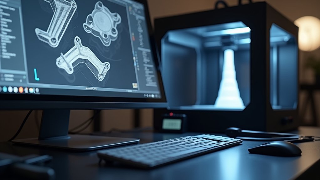
You’ll need to choose CAD software that matches your experience level and can handle photogrammetry data imports for accurate headlight measurements.
Popular options like Fusion 360, SolidWorks, and Tinkercad each offer different feature sets, so compare their modeling capabilities against your project’s complexity.
Once you’ve selected your platform, focus on configuring the essential tools for sketching, extrusion, and shape optimization that’ll help you create a strong, lightweight bracket design.
Software Platform Comparison
Since your CAD software choice directly impacts both design quality and printing success, you’ll want to evaluate several key factors before committing to a platform.
SolidWorks excels in precision engineering with robust simulation tools for stress analysis, making it perfect for brackets that must withstand vibration and impact.
Autodesk Fusion 360 offers cloud-based collaboration and integrated CAM features, streamlining your workflow from design to 3D printer.
Rhino specializes in organic shape modeling, letting you create aesthetically pleasing brackets that complement your vehicle’s curves.
Key evaluation criteria:
- 3D printer compatibility – ensuring seamless file export
- Photogrammetry support – for accurate headlight measurements
- Simulation capabilities – validating structural integrity
- Learning curve – matching your skill level
Your choice determines design possibilities and manufacturing success.
Initial Setup Requirements
Once you’ve selected your CAD platform, proper installation and workspace configuration become your next priority.
Download your chosen software directly from the official website to guarantee you’re getting the latest version with full functionality. During installation, verify your system meets the minimum requirements for smooth operation.
After installation, configure your workspace to optimize efficiency. Set up your default units to match your headlight bracket measurements, typically millimeters for automotive parts.
Familiarize yourself with essential tools you’ll use frequently: sketching for creating base profiles, extruding for adding depth, and modification tools for refining shapes.
Take time to customize toolbars and shortcuts for the features you’ll access most. This initial setup investment will streamline your design workflow throughout the entire bracket creation process.
Creating Initial Bracket Models and Dimensions
Start by capturing burst photos of your headlight from every conceivable angle—front, back, sides, top, and bottom—to build a thorough visual dataset for photogrammetry.
Document every angle with burst photography to create a comprehensive visual foundation for precise photogrammetry modeling.
These images will become your foundation for creating precise 3D models that capture every curve and mounting point.
Import your photos into CAD software and begin modeling the headlight’s exact dimensions.
Don’t rush this step—accuracy here determines your bracket’s perfect fit.
Focus on the unique contours that’ll inform your custom design, creating organic shapes that complement your bike’s aesthetics.
Consider these essential design elements:
- Strength optimization – Your headlight depends on this bracket’s reliability
- Weight reduction – Every gram matters for performance and handling
- Component integration – Plan space for speedometers and additional accessories
- Iterative refinement – Each design revision brings you closer to perfection
Incorporating Organic Shapes and Aesthetic Elements
You can transform your headlight brackets from purely functional components into visually striking elements by incorporating organic shapes that flow naturally with your vehicle’s design.
These curved, nature-inspired forms don’t just enhance aesthetic appeal—they also optimize stress distribution and reduce material weight compared to traditional geometric brackets.
Organic Design Benefits
Nature’s flowing forms offer compelling advantages when designing 3D printed headlight brackets that transcend basic functionality.
You’ll discover organic shapes enhance visual aesthetics while delivering superior performance compared to traditional geometric designs.
When you embrace organic design principles, you’ll reveal these transformative benefits:
- Enhanced durability – Natural stress distribution patterns strengthen your bracket’s structural integrity
- Optimized weight – Iterative shape optimization creates robust yet lightweight structures
- Perfect integration – Advanced CAD modeling tailors organic forms around components like speedometers without sacrificing function
- Creative freedom – Unconventional forms inspire innovative solutions that elevate both style and performance
Your organic designs won’t just mount headlights—they’ll become distinctive artistic statements that showcase modern manufacturing capabilities while maintaining essential mechanical requirements.
Shape Optimization Techniques
Mastering shape optimization techniques transforms your organic headlight bracket concepts into precisely engineered components that balance artistic vision with mechanical performance.
You’ll analyze stress points and pressure distribution throughout your design, identifying areas where material can be removed without compromising structural integrity. This approach creates lightweight brackets that maintain exceptional strength.
Your CAD software becomes essential for manipulating organic curves and refining complex geometries. You’ll iterate through multiple design revisions, adjusting wall thicknesses, adding strategic reinforcement ribs, and optimizing hollow sections to reduce weight while preserving function.
Advanced 3D printing technologies enable you to realize intricate organic shapes impossible with traditional manufacturing. You can incorporate flowing curves, biomimetic structures, and lattice patterns that enhance both aesthetics and performance, pushing creative boundaries in custom automotive components.
Integrating Additional Components Like Speedometers
Many custom headlight bracket projects benefit from integrating additional components like speedometers, which transforms a simple mounting solution into a multifunctional dashboard element.
Consider the Motor Scope Mini for its compact design that seamlessly fits within your bracket’s profile.
Your CAD software becomes essential here—accurately model every dimension to guarantee perfect fitment.
Pay special attention to stress points where additional weight might compromise structural integrity.
Shape optimization techniques help you balance the speedometer’s mass while maintaining bracket strength.
Important integration considerations:
- Prototype extensively to test functionality before committing to final prints
- Design proper pressure distribution around mounting points to prevent cracking
- Account for cable routing to maintain clean aesthetics and functionality
- Plan for maintenance access without requiring complete bracket removal
Testing prevents costly reprints and guarantees reliable performance.
Stress Analysis and Pressure Distribution Testing
Once you’ve designed your integrated bracket with speedometer mounting points, you’ll need to verify its structural integrity through thorough stress analysis.
Load simulations will reveal potential failure points and guarantee your bracket withstands real-world stresses. You should conduct pressure distribution testing to evaluate weight transfer patterns, which helps optimize your bracket’s shape and material selection for reduced weight and increased strength.
Load simulations reveal critical failure points while pressure distribution testing optimizes bracket geometry for maximum strength and minimum weight.
Use finite element analysis (FEA) software to visualize stress concentrations throughout your design. This allows you to make informed geometric adjustments before printing.
Pay special attention to stress points where the speedometer integration creates additional loads that could compromise both components’ integrity. Run iterative design improvements based on your testing results, refining your bracket until it achieves the perfect balance of functionality, aesthetic appeal, and reliable performance.
Design Iteration and Optimization Processes
After completing your stress analysis, you’ll enter the iterative design phase where continuous refinement transforms your initial concept into an optimized headlight bracket. This process demands patience and precision as you balance aesthetics with functionality through multiple revisions.
Shape optimization techniques will help you achieve the perfect strength-to-weight ratio, removing unnecessary material while maintaining structural integrity. Each prototype serves as a vital test for fitment and concept viability, revealing areas needing improvement.
Your optimization process should focus on:
- Eliminating weak points that could cause catastrophic failure during rides
- Reducing weight without compromising the safety of your lighting system
- Improving mounting stability to prevent vibration-induced loosening
- Enhancing durability to withstand harsh weather and road conditions
Continuous collaboration and feedback accelerate refinement, ensuring your final design meets performance standards.
3D Printing Settings and Material Selection
When your bracket design reaches its final form, material selection becomes the foundation of a successful print that’ll withstand real-world mounting conditions.
Choose PLA for straightforward printing, but select ABS or PETG when you need superior durability and heat resistance for automotive applications.
Set your layer height between 0.1mm and 0.3mm—lower heights deliver finer details but extend print times considerably.
Adjust temperatures accordingly: PLA requires 190-220°C, while ABS needs 220-250°C for ideal adhesion and strength.
Print at 30-60 mm/s for better accuracy, especially with intricate organic shapes.
Enable proper bed adhesion by heating to 60°C for ABS materials.
Apply glue stick or painter’s tape for PLA to prevent warping during printing.
Post-Processing and Finishing Techniques
Three critical finishing steps transform your freshly printed headlight bracket from a rough prototype into a professional-grade component ready for installation.
First, you’ll carefully remove support material to preserve the part’s structural integrity.
Next, sand the surface using 100-400 grit sandpaper to eliminate layer lines and create smooth contours. Apply primer before painting to guarantee uniform coverage and superior adhesion.
Consider these essential finishing techniques:
- Vapor smoothing – Creates a glossy, seamless finish that’ll make your brackets look injection-molded
- Clear coat application – Shields against harsh UV rays and environmental damage that could ruin your work
- Resin sealing – Adds incredible strength that’ll withstand years of vibration and road conditions
- Progressive sanding – Achieves that satisfying mirror-like surface you’ll be proud to show off
Testing Fitment and Functionality Validation
Precision testing separates functional brackets from expensive mistakes that’ll leave you frustrated and back at square one.
Start by printing your prototype and testing its fitment against the actual headlight unit. Check clearances, mounting points, and alignment carefully. You’ll quickly identify design flaws that weren’t apparent in CAD.
Physical testing reveals design flaws that CAD software can’t predict—print your prototype and test fitment before committing to final production.
Conduct real-world stress testing by applying pressure at various points to evaluate stress distribution. Note any flex points or weak areas that need reinforcement. Use this feedback to make targeted adjustments in your CAD software.
Refine your design iteratively, making small modifications based on each test cycle. Don’t rush this process—each iteration brings you closer to peak performance.
Once you’ve finalized the bracket, perform a thorough review ensuring any integrated components like speedometers function correctly within your setup.
Frequently Asked Questions
Is There Anything Illegal to 3D Print?
You can’t legally 3D print firearms, copyrighted designs, unapproved medical devices, or drug paraphernalia in most jurisdictions. You’ll face serious legal consequences if you don’t check your local laws before printing.
Can You 3D Print Headlight Lenses?
You can 3D print headlight lenses using transparent materials like PETG or polycarbonate. You’ll need high-resolution printing and post-processing like sanding and polishing to achieve proper optical clarity for effective light transmission.
What Is the Best Glue for ABS 3D Print?
You’ll get the strongest bonds with ABS cement since it chemically melts surfaces together. Alternatively, you can use cyanoacrylate for quick adhesion or epoxy for maximum durability and temperature resistance.
Can I 3D Print Plastic Parts?
You can definitely 3D print plastic parts using materials like PLA, ABS, and PETG. Choose the right plastic for your project’s strength and temperature requirements, then optimize your printer settings for best results.
Leave a Reply