You’ll find that conductive filament resistance varies considerably between brands and orientations—Protopasta’s conductive PLA shows 30 Ω⋅cm horizontally versus 115 Ω⋅cm vertically. Print horizontally when possible since Z-axis resistance can be 300% higher than X/Y directions. Choose thicker filaments for lower resistance, maintain 75-90% infill density, and keep voltages under 60V for safety. Temperature affects conductivity, so control your printing environment carefully. These fundamentals will guide you toward optimizing your conductive prints for maximum performance.
Understanding Resistivity Values Across Different Conductive Filament Brands
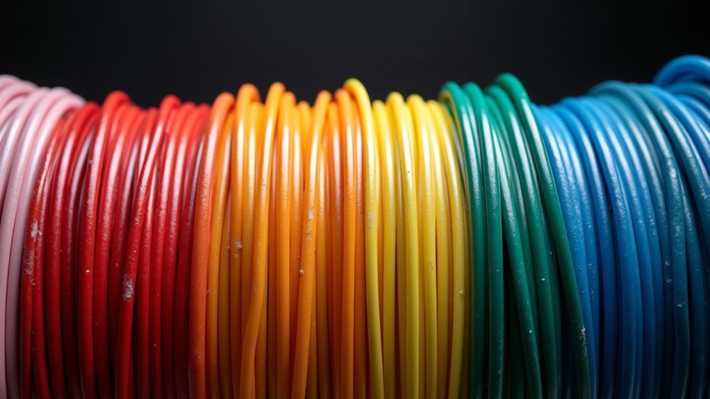
When selecting conductive filaments for your 3D printing projects, resistivity values serve as the primary indicator of how well electricity flows through the material.
You’ll find significant variations across brands and material types. Protopasta Conductive PLA shows 30 Ω⋅cm resistivity along X- and Y-axes, jumping to 115 Ω⋅cm on the Z-axis. In contrast, 3dk.berlin’s 3dkonductive performs better with 24 Ω⋅cm horizontally and 53 Ω⋅cm vertically.
Brand selection significantly impacts conductivity performance, with resistivity differences of up to 300% between horizontal and vertical print orientations across manufacturers.
These directional differences matter for your application’s design. While typical conductive PLA averages around 0.6 Ω⋅cm, actual values vary widely between manufacturers.
You’ll generally find PLA easier to print than ABS, though ABS offers superior thermal resistance. Conductive PLA also provides environmentally friendly benefits due to its biodegradable nature compared to traditional plastics.
Compare specific resistivity data before choosing, as lower values indicate better conductivity for your electronic applications.
Temperature Effects on Conductive PLA Electrical Performance
You’ll find that temperature greatly impacts conductive PLA’s electrical performance in three critical ways.
Production temperatures during manufacturing directly affect your filament’s final resistance values, while measurement temperatures during testing will alter the readings you’re getting. The material exhibits directional resistance variations, with Z-axis conductivity reaching as high as 115 Ω-cm compared to XY plane resistance of up to 30 Ω-cm.
Understanding these thermal effects lets you optimize your designs for consistent electrical performance across different operating conditions.
Production Temperature Impact
Production temperature dramatically influences the electrical performance of conductive PLA filaments, creating a complex relationship between thermal processing conditions and conductivity outcomes.
When you’re extruding at 190-200°C, you’ll notice significant changes in your filament’s rheology and morphology that directly affect electrical properties. Your resistivity can vary dramatically—ranging from 29.38 Ω to 6750 Ω—depending on precise temperature control.
You’ll find that resistivity follows a parabolic function, initially increasing with temperature before decreasing.
Multiple reprocessing cycles will alter your material’s crystallinity, changing both melting points and conductivity. To optimize performance, you must maintain precise extrusion and chamber temperatures while ensuring uniform distribution of conductive additives like carbon black throughout your filament for consistent electrical performance. Testing with force sense resistors can help you measure and validate the electrical properties of your printed conductive components.
Measurement Temperature Effects
Although production conditions establish your filament’s baseline properties, measurement temperature creates dynamic changes in electrical performance that you must account for during actual use.
You’ll observe that conductive PLA’s resistivity follows a parabolic pattern between 22°C to 55°C, initially increasing with temperature before decreasing again. This creates resistivity changes up to 26% across typical operating ranges.
Temperature affects the breakage and reformation of carbon filler networks within your printed parts, altering conductive pathways.
While DC conductivity remains relatively stable with minor deviations of 0.002 S/cm from 10°C to 40°C, the underlying microstructural changes impact overall electrical performance. Room temperature testing should be conducted between 21-22°C with controlled humidity to ensure reproducible measurements.
You’ll need to take into account these temperature-dependent variations when designing sensors or electronics requiring consistent resistance values throughout their operating environment.
Thermal Resistance Optimization
When designing conductive PLA components for thermal applications, maximizing thermal resistance becomes critical since heat buildup directly affects your part’s electrical performance and structural integrity. You’ll want to leverage topology optimization techniques, which can reduce thermal resistance by 5-20% depending on your print orientation.
| Optimization Method | Thermal Improvement |
|---|---|
| Topology optimization | 5-20% resistance reduction |
| Specialized filaments | Significant improvement |
| Ideal orientation | Variable performance gains |
| Parameter tuning | Enhanced thermal properties |
| Design modifications | Up to 20% in specific cases |
You should also consider using thermally conductive filaments for demanding applications, as conductive PLA’s thermal conductivity remains relatively low at 0.13 W/(m.K). Print parameter adjustments and strategic part orientation will further enhance your component’s thermal performance while maintaining electrical conductivity. The Carbon Black enhancement in conductive PLA creates a thermoplastic matrix that provides electro-conductivity but requires careful thermal management to maintain optimal resistance characteristics.
Layer Orientation Impact on Print Conductivity Measurements
Understanding how layer orientation affects print conductivity becomes essential since the directional properties of 3D-printed conductive parts can vary dramatically based on your printing approach.
You’ll find conductive PLA exhibits markedly lower resistivity in the horizontal XY-plane compared to the vertical Z-direction. This occurs because in-layer orientation provides better electrical contact than across-layer bonding.
When you print horizontally, you’re minimizing air gaps between conductive particles within each layer. Protoplant PLA demonstrates this dramatically, measuring 0.3 ohm-m in-plane versus 1.15 ohm-m across layers.
You can optimize conductivity by adjusting layer height to 0.4mm, which balances horizontal and vertical resistivity. Additionally, increasing material flow and infill overlap reduces air gaps, improving layer bonding and overall conductivity performance. The graphitized carbon structure creates electron pathways that enhance both electrical transmission and mechanical strength throughout your printed components.
Comparing Conductive Filament Options: From Protopasta to Electrifi
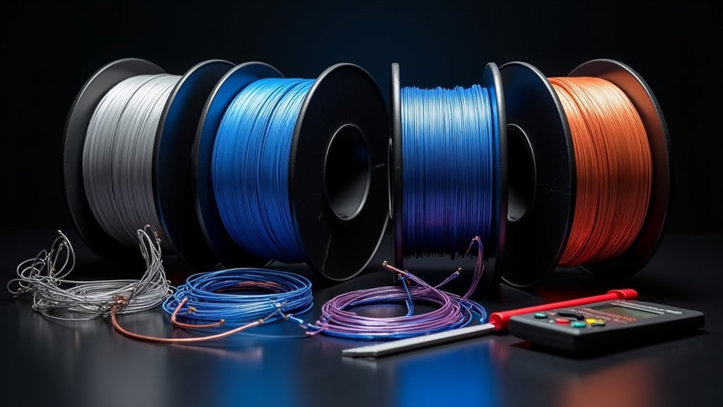
Since conductive filament performance varies considerably between manufacturers, you’ll need to evaluate specific resistance values and material properties before selecting the right option for your project.
Protopasta Conductive PLA offers predictable resistance values: 2.0–3.5 kΩ for 1.75mm filament and 800–1200 Ω for 2.85mm over 10cm lengths. It’s compatible with most PLA-ready printers and works well for low-voltage applications like touch-sensitive devices.
Electrifi and other carbon-filled alternatives typically provide lower resistance per length, making them better for applications requiring higher conductivity. However, they’re often more expensive and may require specialized print parameters. You should consider your printer compatibility, required conductivity levels, and budget when choosing between options.
Remember that thicker filaments always exhibit lower resistance than thinner ones. The material prints with standard PLA settings or hotter temperatures, making it accessible for most users without requiring specialized equipment.
Mechanical Strength Trade-offs When Using Carbon-Enhanced Filaments
Carbon-enhanced filaments create a fascinating engineering paradox: adding conductive particles simultaneously boosts mechanical strength and introduces new structural limitations you’ll need to navigate. You’ll gain superior tensile strength and Young’s modulus along the printing direction, but create anisotropic behavior that weakens perpendicular orientations.
| Property | Along Fiber Direction | Perpendicular Direction |
|---|---|---|
| Volume Resistivity | 47.3 Ω cm | 7.0 Ω cm |
| Tensile Strength | High | Noticeably Lower |
| Young’s Modulus | Enhanced | Reduced |
| Elongation at Break | Improved | Compromised |
| Print Direction Dependency | Ideal | Suboptimal |
You’ll find that higher carbon content increases conductivity but reduces flexibility and increases brittleness. Adding up to 5% thixotropic agents helps maintain shape retention while preserving printability in your composite structures. The incorporation of recycled PLA as a base polymer offers enhanced sustainability while maintaining functional electrochemical performance in additive manufacturing applications.
Voltage Limitations and Safe Operating Parameters for Conductive Prints

When working with conductive 3D printing filaments, you’ll encounter strict electrical boundaries that determine whether your project succeeds or becomes a safety hazard.
Most conductive PLA safely handles up to 60V and 100mA before risking burnout and potentially releasing harmful carcinogens. You can’t treat these materials like traditional conductors – they’re designed for low-power applications.
Your print settings directly affect conductivity. Maintain speeds between 25-45 mm/s for ideal electrical performance, and remember that 1.75mm filament has higher resistance than 2.85mm diameter options.
Layer bonding creates weaker conductivity along the z-axis compared to x/y directions. The conductive additives like carbon black, graphene, and metal powders can increase the brittleness of your printed parts.
- Test electrical properties before deployment to verify manufacturer specifications
- Design power sources with safety margins to prevent overloading
- Consider filament diameter when calculating resistance for your specific application
Piezoresistive Properties and Stress-Induced Resistance Changes
Beyond their basic conductive properties, 3D-printed conductive filaments exhibit piezoresistive behavior – their electrical resistance changes when you apply mechanical stress. This effect occurs because mechanical deformation alters the material’s internal structure, affecting how current flows through conductive pathways.
Your material choice greatly impacts piezoresistive sensitivity. CNT/ABS composites demonstrate high sensitivity and stability, while PLA nanocomposites show potential but may lack consistency during cyclic loading. The gauge factor – measuring sensitivity to strain – varies based on filler content and distribution.
You’ll notice that conductive PLA’s brittleness makes it prone to cracking under stress, potentially causing permanent resistance changes. Interestingly, PLA with multi-walled carbon nanotubes can exhibit a negative pressure coefficient, where resistance actually decreases under compression forces.
Your 3D printing parameters, particularly infill patterns, directly influence these electrical properties. Long-term testing reveals that gauge factors may decrease over time due to material rearrangement and creep effects.
Measuring and Testing Conductive Filament Performance in Your Prints
Since accurate performance evaluation requires proper measurement techniques, you’ll need to understand the fundamental methods for testing conductive filament resistance in your 3D prints.
The four-probe method delivers superior accuracy compared to two-probe setups by eliminating contact resistance issues. When standard multimeters fall short, programmable LCR bridges provide precise measurements for high-resistance materials.
Your testing setup greatly impacts results. Silver paste improves probe-to-filament contact, while heated configurations soften the material for stable connections.
Consider these factors affecting your measurements:
- Infill ratio – Higher percentages typically reduce overall resistance
- Printing conditions – Temperature and extrusion pressure directly influence conductivity
- Material properties – Each conductive filament type exhibits unique volume resistivity characteristics
The piezoresistive properties of conductive filaments enable self-sensing capabilities that can monitor structural changes in your printed components. Conduct repeated tests to verify reliable data and account for material variations in your printed components.
Design Considerations for Z-Axis Conductivity Variations
When designing circuits with conductive filament, you’ll need to account for the notably higher resistance along the Z-axis compared to X/Y directions.
Your print orientation strategy should prioritize routing current paths horizontally through layers rather than vertically between them, since Z-axis resistivity can be 3-4 times higher than X/Y axes.
You’ll also want to plan your circuit paths carefully, keeping critical electrical connections within the same layer whenever possible to avoid the weaker inter-layer bonding that degrades conductivity. For reference applications, this material works well for touch sensor projects and low-voltage Arduino circuits where precise conductivity control isn’t critical.
Layer Adhesion Impact
While conductive filaments excel at transmitting electrical signals within individual layers, they often struggle with vertical conductivity between stacked layers due to poor interlayer bonding.
Poor adhesion creates micro-gaps and voids at interfaces, increasing resistance and limiting current flow along your Z-axis. This variability can cause inconsistent resistance values, impacting your device’s reliability.
You’ll need to optimize several factors to improve layer adhesion and conductivity:
- Maximize infill density (75-90%) to improve vertical material continuity and lower Z-axis resistance
- Fine-tune printing temperature within your filament’s recommended range to guarantee proper layer fusion without degrading conductive pathways
- Minimize retraction distance (0.5-1.0 mm) and control print speed (50-70 mm/s) to reduce layer defects that compromise electrical contact
Additionally, avoiding layer fan usage during printing can significantly enhance adhesion quality and improve interlayer conductivity performance.
Print Orientation Strategy
Beyond addressing layer adhesion challenges, your print orientation decisions fundamentally determine how electrical current flows through your conductive filament parts.
You’ll achieve ideal Z-axis conductivity by aligning filament extrusions parallel to your desired conductive pathways. Vertical or Z-axis parallel orientations produce considerably higher thermal conductivity compared to other orientations, with PLA reaching 0.256 W/mK.
Your infill pattern choices directly impact vertical conductive path continuity. Flat, cross-hatch, and concentric patterns yield different conductivity outcomes due to filament alignment variations.
You must account for anisotropic electrical behavior when designing circuits, as conductivity varies dramatically based on filament direction relative to the Z-axis. Strategic layer height optimization and proper nozzle temperature control reduce Z-axis gaps, enhancing filament connectivity throughout your printed structure. Higher printing layer thickness contributes to increased conductivity due to larger cross-sectional areas of printed lines.
Circuit Path Planning
Since conductive filament exhibits dramatically different resistivity values between the XY plane (30 Ω-cm) and Z-axis (115 Ω-cm), you’ll need to fundamentally redesign your circuit paths to work with these anisotropic properties rather than against them.
Route your traces horizontally whenever possible to exploit the lower XY-plane resistivity. When vertical connections can’t be avoided, increase the cross-sectional area or create multiple parallel paths to reduce cumulative resistance.
You’ll also want to integrate conductive vias or metallic inserts to bridge layers effectively. Some filaments like Multi3D require elevated temperatures between 130-160°C for optimal conductivity, which affects both print settings and thermal management in your designs.
- Design horizontally-dominant paths – Keep circuit traces in the XY plane to minimize resistance and guarantee reliable current flow
- Avoid sharp vertical shifts – Gradual connections and wider vertical traces prevent signal degradation and failure points
- Use metallic bridges – Embedded inserts bypass high-resistance Z-axis filament bonds entirely
Cost-Benefit Analysis: When to Choose Conductive PLA Over Metal Conductors
Three key factors determine whether conductive PLA offers better value than traditional metal conductors: your project’s electrical requirements, manufacturing complexity, and budget constraints.
You’ll find conductive PLA most cost-effective for low-voltage prototyping, educational projects, and touch-sensitive applications where resistance levels in the kilo-ohm range work adequately. It’s typically less expensive per meter than equivalent metal wires and eliminates labor costs for integration into 3D printed parts.
However, you shouldn’t choose conductive PLA for high-current applications or power transmission where copper’s micro-ohm resistivity proves essential. The material’s abrasive nature requires frequent nozzle changes, adding to maintenance costs.
Conductive PLA isn’t suitable for high-current applications where copper’s superior micro-ohm resistivity remains absolutely critical for reliable power transmission.
The material works best when you need rapid prototyping with 2-5 day lead times, integrated structural-electrical designs, or reduced cable clutter in proof-of-concept models requiring minimal post-processing.
Frequently Asked Questions
Can Conductive PLA Be Mixed With Regular PLA to Customize Conductivity Levels?
You can mix conductive PLA with regular PLA to customize conductivity levels. Adjusting the mix ratio controls electrical resistance – more regular PLA increases resistance while reducing cost and brittleness.
How Does Humidity Affect the Storage and Electrical Properties of Conductive Filaments?
Humidity damages your conductive filament by increasing electrical resistance and causing print defects. You’ll need dry storage below 40% humidity and should pre-dry filament before printing to maintain conductivity.
Are There Food-Safe Conductive PLA Options Available for Kitchen Applications?
You won’t find many food-safe conductive PLA options currently available. The conductive additives like carbon typically aren’t food-grade certified, so you’ll need alternatives like PLA+ or PETG for kitchen applications.
Can Conductive Filaments Be Painted or Coated Without Losing Their Electrical Properties?
Painting conductive filaments with standard coatings will block their electrical properties. You’ll need to keep contact areas exposed or use specialized conductive paints to maintain functionality for your circuits.
Do Conductive Filaments Require Special Ventilation During Printing Due to Additives?
You don’t need special ventilation for conductive filaments beyond standard 3D printing practices. While additives may release particles, there’s no specific data indicating they require enhanced ventilation compared to regular filaments.
In Summary
You’ll find that conductive filaments offer unique advantages for prototyping and specialized applications, but they’re not universal replacements for traditional conductors. You’ve got to balance resistance properties, mechanical strength, and cost considerations for your specific project needs. Don’t expect metal-like conductivity, but you can leverage their piezoresistive properties and printability for sensors, heating elements, and educational projects. Test thoroughly and design with their limitations in mind.


Leave a Reply