You can repair STL mesh holes using ten effective methods: manual three-point circle creation for circular openings, automated hole detection algorithms, boundary edge selection with planar mesh generation, extrusion-based gap closure, welding overlapping vertices, normal direction correction using the _Dir command, offset circle sketching for complex geometries, mesh subdivision techniques, patch single face methods, and solid body conversion with wrap functions. These approaches guarantee watertight models ready for 3D printing while preventing costly failures and structural issues that compromise your final output.
Manual Mesh Repair With Surface Projection Techniques

When dealing with complex holes in STL meshes, manual repair using surface projection techniques offers precise control over the closure process.
You’ll start by creating a plane through three strategic points along the hole’s edge, establishing a foundation for your repair sketch. Next, project the boundary points onto this sketch plane to guarantee accurate alignment with your existing mesh geometry.
Use these projected points to define a three-point circle, adjusting with offsets if you need a tighter fit. When you extrude the circle sketch toward the solid body, select the join option to seamlessly integrate new geometry with your STL file.
Create a three-point circle from projected points, then extrude with join option for seamless STL integration.
Finally, inspect the closure area for gaps or misalignments, making adjustments as needed to close holes effectively.
Automated Hole Detection and Filling Algorithms
While manual repair techniques provide precise control, automated hole detection and filling algorithms streamline the mesh repair process by identifying and closing gaps without constant user input.
These algorithms use edge detection and mesh analysis techniques to locate holes in your STL files, greatly reducing manual intervention. You’ll find that machine learning models enhance accuracy, particularly when dealing with complex or irregular geometries.
Several software tools offer automated filling algorithms that integrate seamlessly with various mesh repair workflows, enabling quick hole closure.
However, effectiveness varies based on mesh complexity and the algorithm’s ability to analyze surrounding geometry for appropriate filling strategies.
Three-Point Circle Creation for Circular Openings

For circular openings in your STL mesh, three-point circle creation offers a precise geometric approach that guarantees accurate hole closure.
You’ll start by selecting three distinct points evenly spaced around the hole’s perimeter to accurately capture its curvature. Project these points onto a sketch plane created through them, establishing your working surface.
Use your sketching tools to create the three-point circle, defining it through the projected points. This assures smooth closure that follows the hole’s natural geometry. If dimensional discrepancies exist, you can add an offset to the circle for a tighter fit against the solid body.
Once your circle sketch is complete, extrude it into the solid body. This effectively closes the hole while maintaining proper alignment and integration with your existing mesh structure.
Boundary Edge Selection and Planar Mesh Generation
Since accurate boundary edge selection forms the foundation of successful hole filling, you’ll need to carefully identify the perimeter edges that define each opening in your STL mesh.
Start by locating naked edge borders around holes and duplicating them to create polylines that’ll serve as your capping boundaries.
Once you’ve selected the boundary edges, use PlanarMesh to generate a cap that aligns perfectly with these edges, ensuring seamless closure.
For single holes, apply the _FillMeshHole command to the selected opening, or use FillMeshHoles to address all detectable holes simultaneously.
After creating your cap mesh, check the normals using the _Dir command to verify proper orientation for 3D printing compatibility.
Extrusion-Based Gap Closure Methods
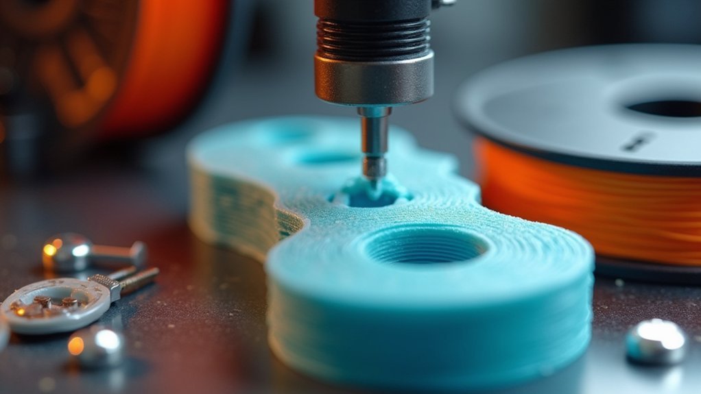
When dealing with larger or irregularly shaped holes that resist traditional mesh filling techniques, extrusion-based methods offer a robust alternative approach.
You’ll start by creating a sketch on a plane that intersects the hole, ensuring proper alignment with surrounding geometry. Use the three-point circle tool to outline the hole based on projected points from your mesh for accurate closure.
When extruding the circle sketch toward the solid body, select the join option to integrate new geometry with existing mesh, preventing separate body creation.
Verify that your extruded section fills the hole completely without gaps or misalignments using visual inspection or slice preview tools.
Finally, confirm your solid body’s watertight status using 3D slicers before printing.
Command-Line Tools for Batch Hole Repair
While extrusion methods work well for individual holes, command-line tools provide a more efficient solution when you’re facing multiple gaps across your STL mesh.
You’ll find _FillMeshHole and FillMeshHoles particularly effective for batch processing without manual intervention on each hole. The _FillMeshHole command lets you target specific holes by selecting boundary edges, while FillMeshHoles automatically detects and fills all gaps in a single execution.
These tools are especially valuable when dealing with STL files containing numerous open holes that complicate 3D printing. For successful results, verify your selected boundary edges form continuous loops, as discontinuities prevent proper functioning.
Open holes in STL files create 3D printing complications, requiring continuous boundary edge loops for successful automated filling.
You’ll enhance your workflow efficiency markedly, especially with complex mesh files requiring repetitive tasks that would otherwise demand considerable manual effort.
Welding and Normal Direction Correction
After repairing holes in your STL mesh, you’ll need to weld vertices and edges together to create a fully connected structure that eliminates gaps.
Use the _Weld command to merge overlapping or nearby vertices, ensuring your mesh maintains structural integrity throughout the model.
You’ll also need to check and correct normal vector alignment with the _Dir command, as improperly oriented normals can cause visual artifacts and printing failures.
Mesh Welding Process
The mesh welding process merges vertices that fall within a specified distance threshold, effectively eliminating gaps and creating the watertight surface you’ll need for successful 3D printing. You’ll use commands like _Weld with specified angle or distance parameters to fuse closely positioned vertices together without compromising your mesh’s overall shape.
During welding, you must pay attention to normal direction correction since inverted normals can cause rendering issues and inaccuracies in your final printed model.
After completing the welding process, you should check your mesh’s normals using the _Dir command to confirm they’re all facing outward, ensuring proper surface integrity.
Effective mesh welding considerably reduces holes and gaps, enhancing your model’s readiness for slicing and printing processes while maintaining dimensional accuracy.
Normal Vector Alignment
Proper normal vector alignment builds upon successful mesh welding to ascertain every face in your STL mesh points consistently outward from the model’s surface. After welding vertices with techniques like _Weld 180 degrees, you’ll need to correct any misaligned normals using tools like the _Dir command.
| Issue | Visual Indicator | Correction Method |
|---|---|---|
| Inverted faces | Dark/black surfaces | Use _Dir command |
| Mixed directions | Patchy appearance | Select all, unify |
| Inconsistent normals | Rendering artifacts | Flip selected faces |
| Watertight failures | Slicer errors | Verify outward pointing |
| Print problems | Failed supports | Check normal consistency |
Incorrect normals cause slicers to misinterpret your model, leading to failed prints with gaps and holes. You must regularly check and correct normal directions before printing to ascertain watertight geometry and successful results.
Offset Circle Sketching for Complex Geometries
When you’re working with complex geometries that have irregular holes, offset circle sketching provides a more sophisticated approach than basic patching methods.
You’ll start by projecting key points from the hole onto your designated sketch plane, guaranteeing accurate alignment with the mesh geometry. Adjust the offset circle’s size to account for material thickness or specific design requirements, which enhances the closure’s fit with existing geometry.
Use the three-point circle method for more precise and smoother closures, as it better adapts to irregular hole contours compared to standard circular sketches.
After creating your offset circle, extrude the sketch toward the solid body with the join option selected for seamless integration.
Finally, verify the alignment and fit post-extrusion to guarantee adequate filling without gaps.
Mesh Subdivision and Patch Single Face Techniques
While offset circle sketching works well for many scenarios, complex holes with irregular boundaries often require a different approach that focuses on mesh-level modifications.
You’ll find mesh subdivision particularly effective for breaking down larger polygons into smaller, manageable pieces that define edges more precisely and improve overall mesh quality.
The Patch Single Face technique works by subdividing irregular hole areas into smaller faces that you can fill more easily. Before applying this method, you must examine edge loops carefully since continuous loops are essential for successful closure.
When creating your mesh cap, verify it remains planar to prevent 3D printing complications.
Combining mesh subdivision with Patch Single Face provides a robust solution for closing intricate holes, ultimately producing watertight models ready for printing.
Solid Body Conversion for Complete Closure
Although mesh subdivision and patch techniques can resolve many hole issues, converting your mesh to a solid body represents the final step in achieving complete watertight closure. This conversion guarantees your model meets 3D printing requirements without errors.
The solid body conversion process involves several critical steps:
- Identify and fill gaps – Locate all holes or openings in your mesh structure that prevent watertight closure.
- Apply repair functions – Use tools like “Wrap” to convert and repair complex geometries automatically.
- Verify edge integrity – Check that no naked edges or unclosed surfaces remain after conversion.
- Test with slicers – Run your solid body through 3D printing software to confirm printability and structural integrity.
You’ll achieve a fully closed, print-ready model that eliminates potential printing failures.
Frequently Asked Questions
How to Close Holes in STL?
You’ll want to first weld your mesh using _Weld, then try _FillMeshHole or FillMeshHoles commands. If automatic filling fails, project boundary points onto sketches and create manual patches using PatchSingleFace.
How to Close Holes in Mesh?
You’ll close mesh holes by using _FillMeshHoles command for automatic detection. Select boundary edges carefully, use _PlanarMesh for complex gaps, apply _Weld to guarantee proper connections, and verify normals with _Dir.
How Do I Close a Mesh Fusion?
You’ll close a mesh fusion by first identifying holes with _ShowEdges, then using _FillMeshHole or FillMeshHoles commands. Make certain you’ve welded the mesh beforehand and check normals afterward using _Dir.
How to Fix Holes in a 3D Model?
You’ll fix holes by using _FillMeshHole for selected gaps or FillMeshHoles for all detectable holes. First, weld your mesh with _Weld 180 degrees, then accurately select boundary edges for successful filling.




Leave a Reply