You’ll transform your 3D printer’s reliability and print quality by installing an automatic bed leveling sensor, which measures bed surface variations at multiple points and compensates for irregularities in real-time. This installation involves mounting sensor brackets, connecting power and signal wires to your control board, updating firmware with ABL support, and calibrating the system through probing procedures. The process eliminates manual leveling while ensuring consistent nozzle-to-bed distance throughout prints, though proper electrical connections and firmware configuration remain essential for peak performance.
Understanding Automatic Bed Leveling Technology and Its Benefits

When you’re dealing with uneven print beds that cause failed prints and wasted filament, automatic bed leveling technology offers a sophisticated solution that transforms your 3D printing experience.
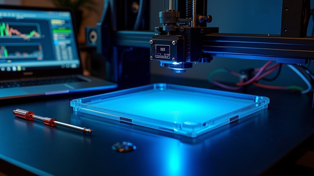
This system uses sensors or probes near your extruder nozzle to measure bed height at multiple points, creating a detailed map of your bed’s surface irregularities. Your printer’s firmware then uses this data to dynamically adjust the Z-axis in real-time, maintaining consistent nozzle-to-bed distance throughout the entire print.
Sensors map bed irregularities while firmware dynamically adjusts Z-axis positioning, ensuring optimal nozzle-to-bed distance throughout every print.
You’ll save significant time by eliminating repetitive manual leveling procedures while achieving better first layer adhesion and improved print quality.
The technology reduces risks of nozzle clogging and scratches, delivering consistent results even when your bed warps over time, making it invaluable for both beginners and professionals. Additionally, the system effectively compensates for surface irregularities that would otherwise compromise print accuracy and adhesion.
Essential Tools and Components for Sensor Installation
Five essential categories of tools and components guarantee your automatic bed leveling sensor installation proceeds smoothly and safely.
You’ll need the sensor module itself, mounting brackets, connection cables, and fasteners for hardware assembly. Basic tools include screwdrivers, Allen wrenches, and a multimeter for electrical verification. A soldering iron becomes necessary if you’re modifying wiring connections.
Your software toolkit requires:
- Compatible firmware – Marlin firmware with ABL support tailored to your printer model
- Configuration software – Tools to input sensor offsets and calibration data
- Backup utilities – Programs to save existing settings before making changes
Safety equipment protects your investment: anti-static wrist straps prevent component damage, while electrical tape insulates connections.
Don’t forget consumables like cable ties for wire management and cleaning supplies for preparing mounting surfaces. Quality signal cables ensure reliable communication between your sensor and printer’s mainboard throughout the leveling process.
Physical Mounting and Bracket Assembly Process

Before you begin attaching any components, position your print head at a comfortable working height and power down your printer completely.
Select a bracket designed specifically for your sensor type and printer model. If standard brackets don’t fit properly, consider using a 3D printed custom mount for better compatibility.
Choose brackets that match your specific sensor and printer model, or opt for custom 3D printed mounts for optimal fitment.
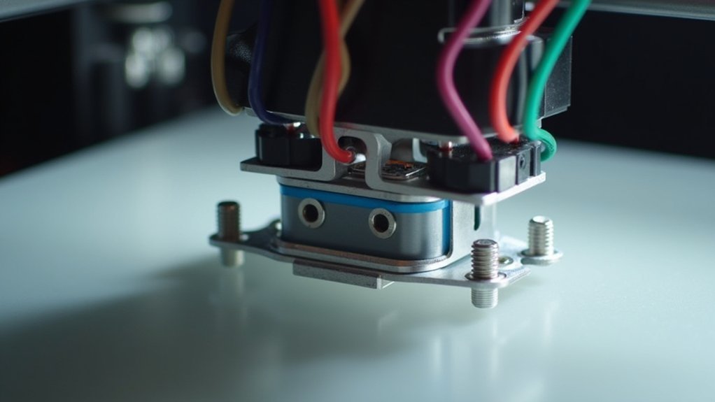
Attach the sensor securely to the bracket using the provided screws or clips, ensuring it won’t shift during printer movement. Choose adjustable brackets when possible to enable fine height tuning later.
Mount the entire assembly adjacent to the print head, typically on the hot end carriage.
Position the sensor’s sensing surface about 3-4 mm above your nozzle tip. Verify the bracket material and shape won’t interfere with printer motion or obstruct bed access near corners.
Double-check that you’ve selected the correct sensor type for your specific printer configuration and bed material, as inductive sensors work with metal surfaces while capacitive sensors can detect various materials.
Electrical Connections and Wiring Configuration
Once your sensor bracket is firmly mounted, you’ll need to establish proper electrical connections between the sensor and your printer’s control board. Most auto bed leveling sensors require three-wire connections: ground, power, and signal.
However, you’ll face voltage compatibility challenges since sensors typically need 6-36V while control boards supply only 5V.
Here’s your wiring checklist:
- Power down completely – Always disconnect printer power before modifying any wiring to prevent component damage or electric shock.
- Use protective circuitry – Install optocouplers or voltage level shifters when connecting higher voltage sensors to prevent board damage.
- Follow color coding – Maintain proper wire sequencing (typically Brown=GND, Red=Power, Orange=Signal) and avoid routing sensor cables near motor or heated bed wiring.
Double-check manufacturer wiring diagrams for your specific sensor model. The auto-leveling sensor replaces the z-end stop connection on your control board for proper functionality.
Firmware Updates and Software Setup Requirements

After establishing proper wiring connections, you’ll need to update your printer’s firmware to enable automatic bed leveling functionality.
Your firmware must support ABL features like Marlin firmware and be configured for your specific sensor type, whether it’s a BLTouch or inductive sensor.
You’ll need a computer with Arduino IDE or VS Code with PlatformIO to edit and flash the firmware.
Before updating, backup your original firmware to prevent bricking your printer.
Configure the firmware with correct sensor offsets and probing parameters, then flash via USB or SD card with stable power.
After installation, enable ABL through printer menus, calibrate Z offset, and run bed probing to create a mesh map. Enable DEBUG_LEVELING_FEATURE in your firmware configuration to provide detailed logging during the homing and leveling process for troubleshooting purposes.
Save settings to EEPROM using the M500 command to retain configurations across restarts.
Calibration Procedures and Testing Methods
Once you’ve installed your bed leveling sensor, you’ll need to calibrate it properly to guarantee accurate probing across your print bed.
Start with the initial sensor setup by positioning it 6 to 6.2 mm above the nozzle tip, then perform a manual paper test to establish baseline measurements before running automated routines. Use bottle caps or printed spacers in each corner to achieve uniform height around the bed during the initial leveling process.
Finally, you’ll validate the mesh grid through multiple probing cycles to confirm your sensor triggers consistently at each point.
Initial Sensor Setup
While proper sensor mounting establishes the foundation for automatic bed leveling, the initial sensor setup requires precise calibration procedures to guarantee accurate height measurements across your print bed.
Start by homing all axes with G28 to establish reference positions before proceeding to sensor calibration. You’ll need to perform coarse manual leveling to bring your bed roughly flat before the auto leveling process begins.
Here’s your essential setup sequence:
- Configure firmware settings – Enable appropriate bed leveling methods and configure probe offsets relative to your nozzle position.
- Adjust trigger height – Fine-tune sensor position while running calibration until it triggers slightly before nozzle contact.
- Save calibration data – Use M500 command to preserve your bed leveling mesh data in EEPROM between power cycles.
After completing the initial setup, verify your calibration accuracy meets the target of 25 microns precision to ensure optimal print quality across the entire bed surface.
Manual Paper Test
Four simple paper test procedures will validate your automatic bed leveling sensor’s accuracy and guarantee proper Z-offset calibration. You’ll home all axes, then move your nozzle to each corner and center point. Slide standard paper between the nozzle tip and bed surface, adjusting until you feel slight friction—this indicates the ideal 0.1mm gap.
| Test Point | Adjustment Method | Expected Result |
|---|---|---|
| Four Corners | Turn leveling screws clockwise/counterclockwise | Consistent paper resistance |
| Center Position | Fine-tune Z-offset in firmware | Uniform nozzle distance |
| Repeat Verification | Check all points after adjustments | Even friction across build plate |
You’ll repeat this process after each adjustment cycle, ensuring consistent tactile feedback. This manual calibration complements your automatic sensor, providing baseline accuracy before mesh leveling activates. Regular maintenance practices help extend your printer’s operational lifespan and maintain calibration stability over time.
Mesh Grid Validation
After completing your manual paper test, you’ll validate the automatically generated mesh grid to guarantee accurate bed compensation across your entire print surface.
The validation process uses dedicated G-code patterns like Marlin’s G26 command to print test grids that reveal over- or under-compensation areas.
Your calibration procedure follows these essential steps:
- Generate baseline data – Run automated probing to create your initial mesh grid
- Print validation patterns – Execute crosshatch or square grid tests to visually confirm mesh accuracy
- Refine iteratively – Adjust mesh points based on test results and repeat until you achieve consistent line width and adhesion
You’ll assess print quality by checking for uniform extrusion, proper adhesion, and absence of gaps or squashing across different bed locations. This automated leveling process significantly reduces the likelihood of print failure compared to traditional manual leveling methods.
Troubleshooting Common Installation Issues
When your automatic bed leveling sensor isn’t working after installation, you’ll likely encounter two primary issues that can derail your entire setup.
Sensor detection problems occur when your printer’s firmware can’t recognize or communicate with the newly installed sensor, leaving you with a non-functional leveling system.
Wiring connection failures represent the most common culprit, where loose cables, incorrect pin assignments, or damaged connections prevent proper signal transmission between your sensor and the control board. Additionally, vibrations from the print head can interfere with sensor readings and cause inconsistent detection during the leveling process.
Sensor Detection Problems
Even with proper installation, automatic bed leveling sensors can develop detection problems that prevent successful leveling routines. These issues often stem from contamination, positioning errors, or mechanical instability that disrupts sensor accuracy.
To diagnose sensor detection problems effectively:
- Test sensor triggering manually – Use a metal object near the sensor to verify it’s working, then check for residual filament on the nozzle or debris on the bed surface that could cause false readings.
- Inspect cable integrity – Move sensor cables during testing to reveal hidden breaks or loose connections that cause intermittent signal drops, especially near moving parts.
- Check mechanical stability – Examine the eccentric nut on the extruder unit and other mechanical components, as loose hardware can cause probe position inconsistencies that prevent accurate bed detection.
- Record leveling sequences – Video your leveling process to identify when and where sensor failures occur, helping isolate systematic errors during probing routines.
Wiring Connection Failures
While proximity sensors may function perfectly during initial testing, wiring connection failures represent the most frequent cause of auto bed leveling malfunctions in 3D printers.
Loose or disconnected wires between your sensor and control board cause signal loss, while flexing cables near the extruder create intermittent breaks. Poor connector seating results in unstable electrical contact, and incorrect pin assignments lead to detection failures.
You’ll often find damaged cables from mechanical stress disrupting sensor communication.
Test functionality by manually triggering your sensor with metal objects, then perform wiggle tests on cables during activation to diagnose intermittent faults. Check for any physical obstructions around the printer that could interfere with wire movement or sensor operation.
Verify correct wiring against your printer’s documentation and clean connectors regularly.
Secure cable paths with clips or sleeves to reduce movement stress and prevent future failures.
Frequently Asked Questions
What Is the Typical Cost Range for Automatic Bed Leveling Sensors?
You’ll find automatic bed leveling sensors range from under $10 for basic capacitive/inductive types to around $110 for premium options like 3D Touch probes with advanced features.
How Long Does a Complete Sensor Installation Usually Take?
You’ll typically complete a sensor installation in 40-90 minutes as an experienced user. If you’re a beginner, expect additional time for troubleshooting, potentially extending the process beyond the standard timeframe.
Can I Install Multiple Sensors on One Printer for Better Accuracy?
You can install multiple sensors, but you’ll need custom firmware modifications and additional hardware capabilities. Most standard printers use one sensor effectively, making multiple sensors unnecessary for typical accuracy improvements.
Do Automatic Bed Leveling Sensors Work With Flexible Print Surfaces?
Yes, you can use ABL sensors with flexible surfaces. Mechanical probes like BLTouch work best since they physically contact the bed. You’ll need stable mounting and proper calibration to guarantee accurate readings.
How Often Should I Replace or Maintain My Bed Leveling Sensor?
You should check your bed leveling sensor monthly during routine maintenance and replace it annually with heavy use. Inspect immediately if you notice failed first layers, sensor errors, or visible damage.


Leave a Reply