You’ll need CAD software like Fusion 360 or FreeCAD to design your custom air intake, then select high-temperature materials like nylon or polycarbonate that can withstand engine bay heat up to 250°C. Use precise measurements with digital calipers to model your vehicle’s intake system, ensuring smooth changes and proper runner lengths for your desired powerband. Print with a large-format printer featuring heated beds, then post-process with sanding and vapor smoothing for best airflow. Proper testing and installation techniques will reveal maximum performance gains.
Understanding Air Intake Design Fundamentals
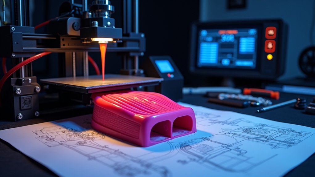
Mastering air intake fundamentals transforms your 3D printing project from a basic replica into a performance-enhancing component. Your intake design directly impacts engine performance by controlling airflow that determines power output and efficiency.
You’ll need to evaluate runner length and shape to tune your powerband—shorter runners boost higher RPMs while longer ones enhance low-end torque.
Focus on creating smooth shifts and consistent cross-sectional areas throughout your intake path. This minimizes turbulence and pressure drop, ensuring ideal airflow reaches the throttle body.
Smooth transitions and uniform cross-sections eliminate turbulence, maximizing airflow efficiency to your throttle body for optimal engine performance.
You can incorporate velocity stacks to accelerate incoming air, which proves essential for high-performance applications.
Pay careful attention to bend placement and orientation—sharp turns disrupt airflow while gradual bends maintain smooth flow into your intake manifold.
CAD Software Selection for Automotive Components
Three critical factors determine your CAD software choice for automotive intake design: simulation capabilities, parametric modeling features, and file export compatibility.
When considering CAD software selection for automotive components, you’ll find professional options like Fusion 360 and SolidWorks excel at airflow analysis and complex parametric modeling. These programs offer robust simulation tools essential for optimizing intake performance.
If you’re starting out, free modeling software like FreeCAD and OnShape provide adequate functionality without expensive licensing costs.
Verify your chosen software exports .STL files for seamless 3D printer compatibility with slicing programs like Ultimaker Cura.
Take advantage of iterative design capabilities to refine your components through multiple revisions.
Community forums and online resources offer valuable troubleshooting support and pre-designed automotive models to accelerate your learning curve.
Material Requirements for High-Temperature Applications
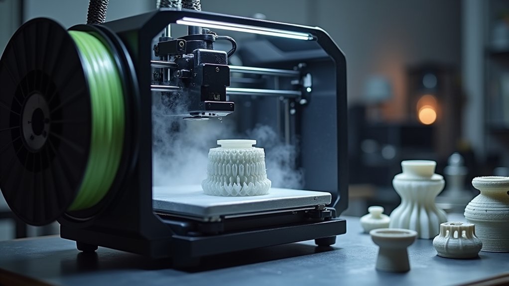
When designing air intake components for automotive applications, you’ll need materials that can withstand the extreme heat generated under the hood. Standard filaments like PLA simply won’t cut it for these demanding environments.
Nylon filament stands out as your best choice, handling temperatures up to 220-230°C with excellent heat resistance. While ABS manages only 192°F (88.9°C), it’s insufficient for high-temperature zones. Polycarbonate offers superior durability compared to standard options.
| Material | Max Temperature | Best Application |
|---|---|---|
| Nylon (PA) | 220-230°C | High-heat components |
| ABS | 88.9°C | Low-heat areas |
| Polycarbonate | 140°C | Structural parts |
| TPU | Variable | Flexible couplers |
Advanced materials like Ultem or carbon fiber composites provide exceptional thermal stability but require specialized equipment and higher costs.
Measuring and Modeling Your Vehicle’s Intake System
You’ll need precise measurements of your existing intake components to create accurate 3D models for printing custom parts.
Start by using calipers or flexible measuring tape to capture exact diameters, angles, and bend curvatures throughout your intake system.
Modern 3D scanning apps can greatly speed up this process while ensuring you don’t miss critical dimensions that affect airflow performance.
Accurate Dimension Collection Methods
Precision forms the foundation of any successful 3D-printed intake component project, and it starts with methodical measurement collection from your vehicle’s existing system. You’ll need digital calipers for small components and a measuring tape for longer sections. Focus on critical dimensions including diameters, lengths, and bend angles to guarantee accuracy in your final design.
| Measurement Type | Tools Required | Key Points |
|---|---|---|
| Diameters | Digital calipers | Inner/outer dimensions |
| Lengths | Measuring tape | Straight sections only |
| Angles/Curves | Angle finder/radius gauge | Bend shifts |
Document each measurement with detailed sketches, noting curve radii for smooth airflow shifts. Cross-reference your data with manufacturer specifications or community-shared dimensions from similar vehicles to validate accuracy before creating your CAD model.
3D Scanning Techniques
Several modern 3D scanning techniques can transform your approach to capturing your vehicle’s intake geometry, moving beyond traditional measurement methods to create highly accurate digital replicas.
These advanced tools generate precise digital models that you can modify for custom parts while dramatically reducing modeling time.
Your scanning options include:
- Dedicated 3D scanners – Deliver exceptional accuracy and resolution for professional-grade results
- Smartphone scanning apps – Provide accessible solutions, though lighting and surface texture affect quality
- Complex part replication – Enable you to recreate damaged or hard-to-find intake components
- Streamlined custom design – Generate editable 3D meshes for CAD software modifications
Remember to clean and properly scale your scanned data to maintain accurate dimensions for successful 3D printing outcomes.
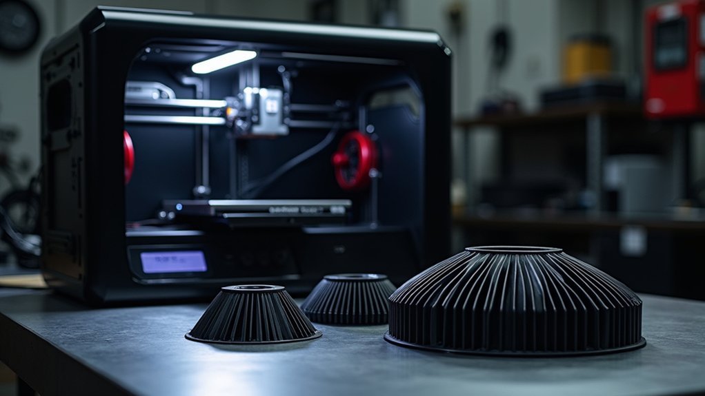
Printer Specifications for Large Format Parts
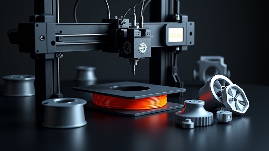
When selecting a 3D printer for custom air intake components, you’ll need a machine with substantial build dimensions to handle the size requirements of these automotive parts.
Look for printer specifications that include a build volume of at least 300 x 300 x 400 mm to accommodate larger components effectively.
Choose printers equipped with heated beds and enclosed chambers to prevent warping during extended prints with ABS or nylon materials.
A direct drive extruder system guarantees proper material flow when printing flexible TPU couplers.
You’ll also need high-temperature nozzles made from stainless steel or hardened steel to handle durable materials like nylon that withstand engine bay heat.
Optimize your slicing settings with 1.0 mm layer heights and 50-60 mm/s print speeds for efficient large-format printing.
Filament Properties and Performance Comparison
Material selection dramatically impacts your air intake component’s performance and longevity under demanding automotive conditions.
Your choice of filament determines whether your custom intake thrives or fails when exposed to engine bay heat and pressure.
Consider these critical performance differences:
- PLA – Cost-effective but deforms under heat, risking catastrophic failure during operation.
- ABS – Withstands 192°F but demands controlled printing to prevent warping frustration.
- Nylon (PA) – Delivers exceptional durability up to 230°C for high-performance applications.
- Ultem – Premium choice offering superior resilience under extreme pressure and temperature fluctuations.
TPU provides flexibility for couplers but lacks structural rigidity.
While ABS offers decent heat resistance, advanced materials like Ultem and Delrin consistently outperform it in printed intake applications, justifying their higher cost.
Print Settings Optimization for Durability
After selecting your filament, refining print settings becomes the decisive factor between a reliable air intake component and a costly failure.
You’ll want to increase layer height to 0.2 mm for faster printing parts while maintaining adequate strength, as thicker layers enhance adhesion and reduce delamination risk.
Set your infill percentage between 50-100% to improve structural integrity, providing better resistance to pressure and heat.
Lower your print speed to 30-50 mm/s for enhanced layer adhesion and reduced warping risks.
Enable a heated bed at 90-110°C for ABS to prevent warping, maintaining consistent temperature throughout printing.
Consider running a temperature tower test to find your filament’s ideal nozzle temperature, achieving the best balance between adhesion and quality.
Post-Processing Techniques for Smooth Airflow
You’ll need to smooth your printed intake components to achieve ideal airflow performance.
Acetone vapor smoothing dissolves ABS surface layers to create glass-like finishes, while strategic sanding of internal surfaces removes layer lines that cause turbulence.
Heat treatment with a heat gun can reshape problem areas and eliminate irregularities that disrupt air movement through your custom intake system.
Acetone Smoothing Methods
Since acetone vapor dissolves ABS plastic’s outer layer, acetone smoothing transforms rough 3D-printed air intake components into polished parts with superior airflow characteristics.
You’ll achieve professional results by following this acetone smoothing process:
- Place your ABS part in a sealed container with a small amount of acetone.
- Allow vapor exposure for 10-20 minutes, monitoring closely to prevent excessive melting.
- Watch for ideal smoothness while ensuring internal structures remain intact.
- Air dry completely before installation to eliminate residual acetone and harmful fumes.
This technique doesn’t just enhance your part’s appearance—it minimizes turbulence within airflow paths, potentially boosting engine performance and efficiency.
The dissolved outer layer creates seamless surfaces that allow air to flow more smoothly through your custom intake components, delivering the professional-grade results your project deserves.
Sanding Internal Surfaces
Use sanding sponges or rotary tools with appropriate attachments to access tight spaces and achieve uniform results on curved surfaces.
These tools provide better control than traditional sandpaper when working inside complex geometries.
Clean components thoroughly after sanding to remove all dust particles that could obstruct airflow or damage your engine.
Experiment with different sanding techniques and grit progressions to find the perfect balance between surface smoothness and structural integrity for maximum intake performance.
Heat Treatment Benefits
While surface sanding improves the exterior finish of your 3D-printed intake components, heat treatment tackles the internal structure to enhance both performance and durability.
This essential post-processing step transforms your printed parts into professional-grade components that’ll withstand demanding under-hood conditions.
Heat treatment delivers four game-changing benefits:
- Stress Relief – Eliminates internal tensions that cause warping during operation
- Enhanced Heat Resistance – Increases deflection temperature beyond 192°F for extreme environments
- Improved Layer Adhesion – Strengthens bonds in nylon and polycarbonate materials
- Structural Integrity – Creates components that maintain shape under thermal cycling
Monitor temperatures carefully during heat treatment to prevent overheating.
Materials like ABS respond exceptionally well to controlled heating, becoming more suitable for high-temperature applications while maintaining ideal airflow characteristics.
Testing and Validation Methods
After designing and printing your custom air intake components, you’ll need to rigorously test them to confirm they meet performance and safety standards. Start with thermal testing by measuring temperature ranges up to 250-260°C to ascertain no deformation occurs. Use CFD analysis to optimize airflow characteristics and examine bend placement for smooth shifts. Conduct pressure pulse testing to simulate real-world engine dynamics and assess component durability.
| Testing Method | Purpose | Success Criteria |
|---|---|---|
| Thermal Testing | Heat resistance validation | No deformation at 250-260°C |
| CFD Analysis | Airflow optimization | Smooth shifts, minimal turbulence |
| Pressure Pulse | Durability assessment | Withstands operational pressures |
| Road Testing | Real-world validation | Performance improvements confirmed |
| Community Feedback | Design refinement | Positive user experiences |
Install components for road testing and gather automotive community feedback to refine your designs.
Installation Considerations and Compatibility
When you’re ready to install your 3D-printed air intake components, you’ll need to guarantee they integrate seamlessly with your vehicle’s stock airbox and throttle body connections.
You must carefully position the MAF sensor—often requiring slight rotation—to maintain smooth airflow and accurate readings throughout the system.
Don’t overlook filter compatibility requirements, as your custom components need to accommodate both OEM and aftermarket filter options without compromising performance.
Stock Component Integration
Since custom 3D-printed air intake components must work seamlessly with your vehicle’s existing systems, you’ll need to focus on precise fitment and compatibility from the design phase forward.
Effective stock component integration requires careful attention to several critical areas:
- Align perfectly with your stock airbox and throttle body – preventing gaps that could cause vacuum leaks or performance issues.
- Adjust MAF mount positioning through slight rotation – ensuring ideal airflow readings and engine management.
- Verify compatibility with existing filters like Burger Motorsports – avoiding costly reinstallation headaches.
- Smooth shift areas between elbows and flanges – maximizing airflow efficiency and power gains.
You’ll also need to select heat-resistant filaments that can withstand engine bay temperatures, as stock components typically handle much higher thermal loads than standard printing materials.
MAF Sensor Positioning
Three critical measurements determine whether your 3D-printed MAF sensor housing will deliver accurate airflow readings or create performance-robbing turbulence. You’ll need to position your sensor at least 12 inches from intake bends, align it precisely with throttle body specifications, and guarantee smooth airflow shifts at all junctions.
| Position Factor | Critical Distance/Angle |
|---|---|
| Bend clearance | 12+ inches upstream |
| Rotation angle | Factory specifications |
| Flange alignment | Zero gap tolerance |
| Material selection | Heat-resistant polymer |
| Airbox transition | Smooth radius curves |
Your MAF sensor positioning directly affects engine performance. When designing custom housings, you’ll want to maintain factory mounting angles while incorporating slight rotational adjustments for ideal fit. Use heat-resistant materials that won’t deform under high temperatures, compromising your sensor’s calibrated position and accuracy.
Filter Compatibility Requirements
Your filter selection determines whether your custom 3D-printed intake delivers enhanced performance or creates costly airflow restrictions. Meeting filter compatibility requirements starts with precise diameter measurements—your intake tube must match the stock filter size of approximately 4.65 inches for ideal airflow and ECM recalibration.
Consider these critical compatibility factors:
- Stock filter dimensions – Measure twice, print once to avoid expensive reprints.
- Aftermarket options – Test compatibility with performance filters like Burger Motorsports.
- Sealing surfaces – Guarantee smooth, even contact points prevent unfiltered air entry.
- Mounting security – Design robust connections that won’t fail under engine vibration.
You’ll achieve better results by designing your intake around proven filter specifications rather than forcing incompatible combinations that compromise performance.
Performance Monitoring and Adjustments
After installing your custom 3D printed air intake components, you’ll need to monitor their performance closely to guarantee they’re operating within safe parameters and delivering the expected results.
Temperature management is essential—keep intake temperatures below 155°F to preserve material integrity, especially for ABS and PLA filaments. Use a thermometer to check under-hood temperatures, ensuring components can handle up to 250-260°C in summer conditions.
Conduct airflow testing with simulation software to analyze design adjustments and optimize throttle body airflow.
Watch for pressure pulses that could cause fatigue issues in printed intakes. Regular performance monitoring helps identify problems early.
Engage with community feedback to learn from shared experiences and make necessary adjustments for improved durability and airflow efficiency.
Frequently Asked Questions
Is It Illegal to 3D Print a Glock Lower?
You can legally 3D print a Glock lower receiver for personal use in most US states, but you’ll need to check your local laws since some states specifically prohibit homemade firearms.
How Much HP Does a Custom Air Intake Add?
You’ll typically gain 5-20 horsepower from a custom air intake, with most seeing 10-15% increases. Your actual gains depend on engine size, existing restrictions, and whether you’ve made other performance modifications.
Is It Legal to 3D Print Replacement Parts?
You can legally 3D print replacement parts for personal use in most jurisdictions, but you’ll need to avoid patent infringement and check local automotive regulations for safety-critical components.
What Is the 45 Degree Rule for 3D Printing?
You’ll need support structures for overhangs steeper than 45 degrees from vertical. This rule prevents sagging and print failures since layers can’t adequately support material at steeper angles during printing.

Leave a Reply