You’ll optimize direct metal laser sintering by positioning parts at 45+ degree angles to minimize supports, selecting materials like AlSi10Mg for lightweight designs or Ti6Al4V for medical applications, and maintaining minimum wall thicknesses of 0.8mm. Design self-supporting features, create 2-5mm escape holes for powder removal, and use simulation tools to predict stress distribution. Implement post-processing steps including heat treatment and surface finishing to reduce internal stresses and enhance material properties for superior mechanical performance.
Optimize Part Orientation and Layout on the Build Platform
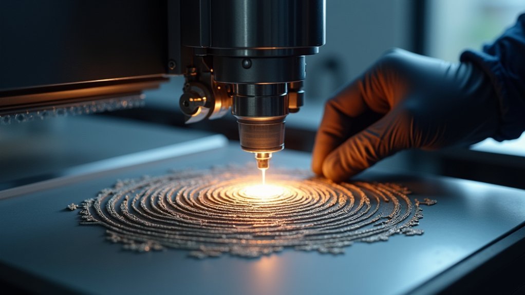
One of the most critical decisions you’ll make in direct metal laser sintering is how you orient and position your parts on the build platform.
To enhance part orientation, position overhangs at angles greater than 45 degrees to minimize support structures, reducing material waste and post-processing time.
Focus on thermal management by orienting parts to minimize thermal gradients, which reduces internal stresses and warping.
Orient tall or thin parts vertically to improve stability and enhance layer adhesion.
When planning your layout, maximize the build platform’s scanning area while maintaining at least 0.5 mm spacing between features to prevent fusion issues.
Position critical surfaces strategically to guarantee ideal laser exposure and minimize visible layer lines through reduced stair-stepping effects.
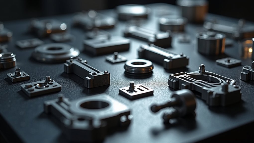
Select the Right Material for Your Application Requirements
After optimizing your part orientation and layout, material selection becomes your next fundamental decision that’ll determine your project’s success.
DMLS offers diverse metal 3D printing materials, each engineered for specific applications. You’ll need to match your material choice with performance requirements to achieve ideal results.
Consider these material-application pairings for your DMLS projects:
- Aluminum alloys (AlSi10Mg) – Choose for lightweight designs requiring thin walls and fine features
- Inconel 718 – Select for aerospace applications demanding high-temperature resistance and corrosion protection
- Titanium alloy (Ti6Al4V) – Opt for biocompatible medical implants ensuring tissue compatibility
- Stainless steel (316L) – Use for industrial components requiring durability in harsh environments
- Copper alloys – Ideal for thermal conductivity applications like heat exchangers and induction coils
Design Self-Supporting Features to Minimize Support Structures
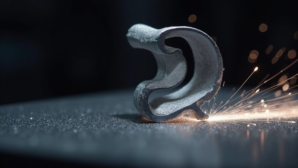
Since support structures can markedly increase your post-processing time and material costs, you’ll want to design self-supporting features that work with DMLS physics rather than against them.
Design features with self-supporting angles of 45° or more to eliminate additional supports during printing. Add fillets or chamfers in overhanging areas to enhance structural integrity while reducing support material requirements.
Self-supporting angles of 45° or greater eliminate the need for additional support structures during DMLS printing operations.
Keep overhang lengths under 0.5 mm without support, as longer spans compromise dimensional accuracy. Confirm horizontal surfaces include adequate support elements to prevent sagging or collapse.
Incorporate internal features like channels or hollow sections to reduce weight and facilitate powder removal. These design strategies maintain part stability during printing while minimizing post-processing requirements.
Maintain Proper Wall Thickness and Feature Sizing
You’ll need to carefully consider wall thickness and feature sizing to make certain your DMLS parts print successfully without failures.
Your walls must meet minimum thickness requirements – typically 0.8mm for basic walls, scaling up to 1.2mm for unsupported sections.
You should also size structural features at least 1.5mm to assure they’ll form properly during the sintering process.
Minimum Wall Thickness Requirements
When designing parts for Direct Metal Laser Sintering, maintaining proper wall thickness becomes critical for preventing structural failures during the printing process.
You’ll need to follow specific minimum wall thickness guidelines to guarantee your DMLS parts maintain structural integrity throughout production. The baseline minimum wall thickness should be 0.8 mm, though this varies based on support conditions and feature types.
Your design approach must differentiate between supported walls and unsupported walls to achieve robust part performance.
Here’s what you need to take into account:
- Supported walls require minimum 1 mm thickness for adequate stability
- Unsupported walls need at least 1.2 mm thickness to prevent breakage
- Structural feature sizes should measure minimum 1.5 mm for strength
- Cosmetic feature sizes can be reduced to 0.75 mm
- Consistent thickness improves accuracy and reduces internal stresses
Structural Feature Size Limits
While wall thickness forms the foundation of DMLS design, structural feature sizing determines whether your parts can withstand operational stresses and maintain dimensional accuracy throughout the printing process.
You’ll need to maintain a minimum feature size of 1.5 mm for structural elements to prevent printing inaccuracies and guarantee your metal components retain their intended strength. When designing load-bearing features like ribs, bosses, or connecting elements, don’t go below this threshold or you’ll risk compromised structural integrity.
Smaller structural features create internal stresses during the DMLS process, leading to warping and dimensional inconsistencies.
You’ll also face challenges with support structures when features are too small. Keep wall thickness consistent across structural elements to minimize these issues and achieve reliable, dimensionally accurate parts that meet your performance requirements.
Plan for Effective Powder Removal in Complex Geometries
Complex geometries in DMLS parts present unique challenges for powder removal, requiring strategic design considerations from the initial planning phase.
You’ll need to implement specific strategies to guarantee trapped powder doesn’t compromise your Direct Metal Laser Sintering results or part functionality.
When designing complex metal parts, focus on creating accessible pathways for powder removal throughout your geometry. Your internal channels should maintain at least 1mm diameter, while escape holes of 2-5mm facilitate effective cleaning.
Part orientation greatly impacts powder accessibility, so position your designs to minimize trapped areas. Hollow sections reduce material usage while improving powder removal efficiency. The DMLS process demands careful attention to support features and channel shapes.
- Design teardrop or diamond-shaped internal channels for enhanced flow and powder removal
- Include hollow sections to reduce material consumption while maintaining structural integrity
- Add removable plugs or extractable features for clearing residual powder from cavities
- Optimize part orientation to minimize powder entrapment in overhangs and intricate areas
- Create escape holes of 2-5mm diameter in complex geometries for effective post-processing
Control Internal Stresses Through Strategic Design Choices
You’ll need to minimize stress concentration points throughout your DMLS part by maintaining uniform wall thicknesses around 1 mm and adding fillets or chamfers to sharp corners.
Strategic geometry optimization involves avoiding large unsupported spans and incorporating escape holes in hollow sections to facilitate powder removal.
These design choices distribute internal stresses more evenly and prevent warping during the sintering process.
Minimize Stress Concentration Points
Since the Direct Metal Laser Sintering process involves rapid heating and cooling cycles that create internal stresses throughout your part, you must design with stress concentration points in mind from the earliest stages.
DMLS stress concentration occurs at sharp changes and abrupt geometry alterations, making gradual shifts between thick and thin sections essential. You’ll want to incorporate design features like fillets and rounded edges that distribute stress evenly throughout your part.
Strategic placement of internal channels and voids helps alleviate stress while maintaining structural integrity.
- Analyze part orientation and support structure placement to prevent uneven thermal gradients
- Use simulation tools to predict stress distribution before printing begins
- Create gradual shifts between varying wall thicknesses
- Incorporate rounded edges and fillets in all geometric features
- Position internal voids strategically to reduce weight without compromising strength
Optimize Part Geometry
While minimizing stress concentration points forms the foundation of DMLS design, optimizing your part’s overall geometry takes stress management to the next level through deliberate structural choices. Strategic part geometry modifications directly control internal stresses while enhancing structural integrity.
| Design Strategy | Stress Reduction Benefit |
|---|---|
| Hollow geometries with internal channels | Improved heat dissipation, reduced thermal stress |
| Self-supporting 30°+ angles | Eliminates support structures and stress concentrations |
| Consistent 1-1.2mm wall thickness | Enhanced structural integrity, minimized breakage |
You’ll achieve superior results by incorporating hollow geometries that reduce material volume while facilitating heat flow. Internal channels serve dual purposes: weight reduction and thermal management. Eliminate unnecessary support structures by designing self-supporting features, then validate your geometry using simulation tools to analyze stress distribution before printing begins.
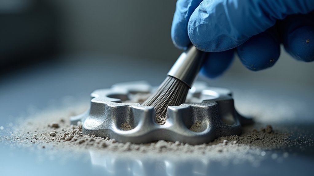
Implement Post-Processing Steps for Enhanced Surface Quality
Although DMLS produces functional parts straight from the printer, implementing targeted post-processing steps will dramatically improve your surface quality and overall part performance.
Heat treatment relieves internal stresses while enhancing mechanical properties. Media blasting effectively smooths rough surfaces, and bead blasting delivers finer finishes for improved aesthetics. Hot isostatic pressing increases density by reducing porosity, ensuring superior mechanical performance.
Always remove residual powder and contaminants before applying coatings to guarantee ideal adhesion.
- Heat treatment protocols – Reduce internal stresses and enhance material properties for specific applications
- Surface finishing hierarchy – Progress from media blasting to bead blasting for increasingly refined textures
- Tumbling operations – Process multiple parts simultaneously using ceramic abrasives for uniform results
- HIP integration – Schedule hot isostatic pressing strategically to maximize density improvements
- Cleaning validation – Establish thorough powder removal procedures before secondary processes
Frequently Asked Questions
What Is the Process of Direct Metal Laser Sintering?
You’ll upload your 3D model, which gets sliced into layers. The machine spreads metal powder, then a laser melts it layer-by-layer. You’ll remove supports afterward and perform post-processing for better finish.
What Is the Tolerance of Direct Metal Laser Sintering?
You’ll achieve tolerances of approximately ±0.2% of nominal dimensions with DMLS, typically ranging from 0.1 to 0.2 mm. Tighter tolerances are possible but markedly increase costs and should be reserved for critical features only.
What Are the Disadvantages of Laser Sintering?
You’ll face support structure requirements, internal stresses causing warping, limited resolution around 1.5mm, slower production speeds, and poor surface finish with visible layer lines requiring additional post-processing work.
What Are the Advantages of Direct Metal Laser Sintering?
You’ll create complex geometries impossible with traditional machining while achieving 99% density and ±0.003 inch tolerances. You can rapid prototype, produce low-volume runs cost-effectively, and work with various materials including titanium and Inconel.


Leave a Reply