You’ll start by selecting appropriate CAD software like AutoCAD, Revit, or Rhino to design your structural models, then export files in STL or OBJ formats for 3D printer compatibility. Choose your printing technology based on project requirements—SLA for high detail, FDM for cost-effectiveness, or SLS for robust functional parts. Optimize slicing parameters including layer height, infill density, and support structures while considering material properties like tensile strength and durability. Our extensive guide covers advanced optimization techniques and testing methods.
Understanding 3D Printing Technology for Structural Engineering Applications

Revolution in construction has arrived with 3D printing technology, transforming how you’ll approach structural engineering projects.
You’ll create complex building components using concrete and metal alloys that weren’t possible with traditional methods. The process begins when you design digital models in CAD software, then translate them into printable formats for precise layer-by-layer construction.
You can choose between extrusion-based printing and powder bed fusion techniques, each offering distinct advantages in speed, resolution, and material compatibility.
You’ll benefit from reduced material waste and faster construction times, making your projects more cost-effective.
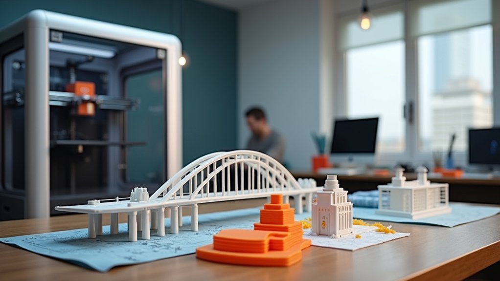
Real-world applications prove 3D printing’s effectiveness – you’ll see intricate pedestrian bridges and building facades demonstrating structural engineering innovation that’s reshaping the construction industry.
Essential Software Tools for Digital Model Design and Preparation
You’ll need to select appropriate CAD software that matches your structural modeling requirements and project complexity.
Converting your digital designs into printer-compatible file formats like STL or OBJ guarantees seamless communication between your modeling software and 3D printer.
Optimizing slicing parameters such as layer height, infill density, and support structures directly impacts your model’s structural integrity and printing success.
CAD Software Selection
When selecting CAD software for structural engineering models destined for 3D printing, you’ll need to balance design capabilities with manufacturing requirements.
AutoCAD excels at precise 2D drafting and basic 3D modeling, while Revit offers extensive BIM functionality that integrates complex structural data and facilitates team collaboration.
Rhino provides advanced surface modeling capabilities ideal for complex geometries.
You’ll want to take into account your specific printing technologies when choosing software. Verify your selected CAD platform can export compatible file formats like STL or OBJ for seamless integration with slicing software such as Cura or PrusaSlicer.
Focus on programs that support design factors essential for 3D printing, including proper wall thickness calculations, support structure planning, and assembly requirements that’ll streamline your manufacturing process.
File Format Conversion
Once you’ve created your structural model in your chosen CAD software, converting it to the proper file format becomes your next priority.
File format conversion transforms your computer-aided design (CAD) files into 3D printer-compatible formats, typically STL or OBJ. STL remains the most widely supported format across different 3D printing platforms, though OBJ files offer color information if needed.
During conversion, you’ll need to specify resolution settings that balance file size with model detail. Higher resolutions capture intricate structural elements but create larger files that slow processing.
Most CAD programs include built-in export functions for these formats, though you might need specialized conversion software for complex models.
Verify your converted file maintains geometric integrity by checking that all surfaces translate properly and no structural details are lost during the process.
Slicing Parameter Optimization
After converting your files, slicing software transforms your 3D model into printer-readable instructions by dividing it into horizontal layers.
You’ll need to optimize several critical parameters that directly impact your structural engineering model’s quality and performance.
Key slicing parameters you should adjust include:
- Layer height – Smaller layers create finer details but extend print time; larger layers print faster with reduced surface quality
- Print speed – Balance between efficiency and precision for your specific structural requirements
- Infill density – Higher percentages increase strength but consume more material and time
- Support structures – Essential for overhangs and complex geometries in engineering models
You’ll also want to configure temperature settings and cooling rates specific to your chosen material, preventing warping while ensuring proper layer adhesion throughout the printing process.
Selecting the Right 3D Printing Technology for Your Project Requirements
You’ll need to evaluate different 3D printing technologies against your specific project demands to make the right choice for your structural engineering models.
Start by examining whether you’re prioritizing fine detail and smooth finishes, functional strength and durability, or cost-effectiveness for larger prototypes.
Understanding the trade-offs between printer costs, material properties, and output quality will guide you toward the technology that best matches your project’s goals and budget constraints.
Technology Comparison Overview
When choosing the ideal 3D printing technology for your structural engineering models, you’ll need to evaluate several critical factors that directly impact your project’s success.
Unlike traditional construction methods, 3D printing offers multiple technological approaches, each with distinct advantages.
Consider these key comparison factors:
- Detail Requirements – SLA delivers exceptional resolution for presentation models, while FDM suits basic prototyping needs.
- Material Strength – SLS produces robust functional parts from powdered materials, whereas Binder Jetting creates colorful but brittle structures.
- Project Scale – Large-scale models benefit from cost-effective FDM, while intricate geometries require SLA precision.
- Budget Constraints – Entry-level FDM printers start under $1,000, while industrial SLS systems exceed $100,000.
Matching your specific project requirements to the appropriate technology guarantees ideal quality and cost-effectiveness for your structural engineering applications.
Project Requirements Assessment
Before selecting your 3D printing technology, define your project’s fundamental parameters to guarantee ideal results.
Start by evaluating your model’s scale and complexity—FDM works best for larger, simpler structures, while SLA excels at intricate, high-resolution designs. For complex structures requiring exceptional detail, consider the superior precision SLA offers.
Evaluate your material needs based on structural requirements. Concrete suits building components, while polymers work perfectly for rapid prototyping.
Budget considerations matter greatly, as industrial SLS systems cost $30,000-$100,000+, whereas entry-level options start at hundreds.
Consider finish quality expectations and post-processing time. SLA delivers smooth surfaces ideal for presentations, while FDM typically requires additional finishing.
Finally, factor in project timelines—binder jetting enables faster full-color model production when speed’s essential.
Cost Vs Quality
Your technology choice directly impacts both your budget and final model quality, making this balance the most critical decision in your 3D printing project.
The cost vs quality equation varies considerably across different printing technologies, and you’ll need to evaluate which approach best serves your structural engineering requirements.
Consider these key factors when weighing your options:
- FDM printers start at hundreds of dollars but offer lower resolution for basic concept models.
- SLA technology delivers superior detail and smooth finishes, though equipment costs begin at several thousand dollars.
- SLS systems provide robust materials used for functional parts, starting around $30,000 for industrial units.
- Binder Jetting creates full-color models affordably but produces brittle parts unsuitable for structural testing.
Match your technology selection to your project’s functional requirements and available budget.
Material Properties and Selection Criteria for Structural Models
Since structural models must withstand various loads and environmental conditions, you’ll need to carefully evaluate material properties before selecting the ideal 3D printing medium for your project. Consider tensile strength, compressive strength, and durability to guarantee accurate real-world performance representation.
| Material | Tensile Strength | Weight | Cost |
|---|---|---|---|
| Steel | High | Heavy | High |
| Aluminum | Medium-High | Light | Medium |
| ABS Polymer | Medium | Light | Low |
| PLA Polymer | Low-Medium | Light | Low |
Don’t overlook thermal properties, as temperature fluctuations can affect model stability. Advanced options like fiber-reinforced polymers offer enhanced performance characteristics but increase complexity and cost. Your material choice greatly influences weight, printing feasibility for complex geometries, and overall project budget. Always conduct mechanical testing before real-world applications to guarantee quality and reliability of your 3D printing results.
Design Optimization Techniques for 3D Printing Compatibility
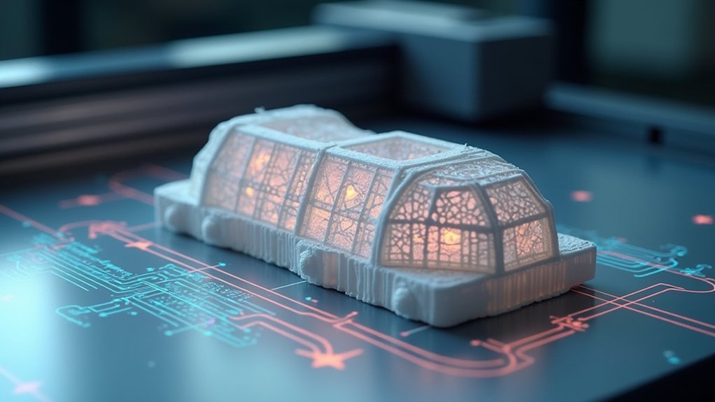
Several key optimization strategies can transform your 3D printed structural models from basic prototypes into high-performance engineering tools.
Design optimization techniques require careful consideration of the additive manufacturing process to maximize your model’s effectiveness while minimizing material waste.
Strategic design optimization balances manufacturing constraints with performance goals, transforming raw concepts into efficient, high-performing structural solutions.
Key approaches include:
- Wall thickness optimization – Balance structural integrity with material efficiency by adjusting thickness based on load requirements.
- Internal lattice integration – Reduce weight while maintaining strength through strategic internal support structures.
- CAD software utilization – Leverage specialized 3D printing modules for automated compatibility adjustments and design validation.
- Finite element analysis implementation – Identify stress concentrations early to guide strategic design modifications.
You’ll need to understand your chosen technology’s specific limitations, including layer height and resolution capabilities.
This ensures your final design meets both performance standards and aesthetic requirements for successful structural engineering applications.
Preparing CAD Files and Converting to Printable Formats
Once you’ve optimized your structural engineering design for 3D printing compatibility, the next step involves preparing your CAD files for the actual manufacturing process.
Begin by confirming your CAD software geometry meets engineering specifications and 3D printing requirements. Export your completed design in STL or OBJ format to convert the model into a printable mesh.
Use slicing software to transform this file into printer-readable instructions, setting critical parameters like layer height, print speed, and support structures. Verify your model’s scaling accuracy to prevent assembly issues.
Conduct thorough error checking for non-manifold edges and intersecting geometries that could compromise structural integrity. These preparation steps confirm successful translation from digital design to physical prototype.
Scaling Considerations and Dimensional Accuracy in Model Creation
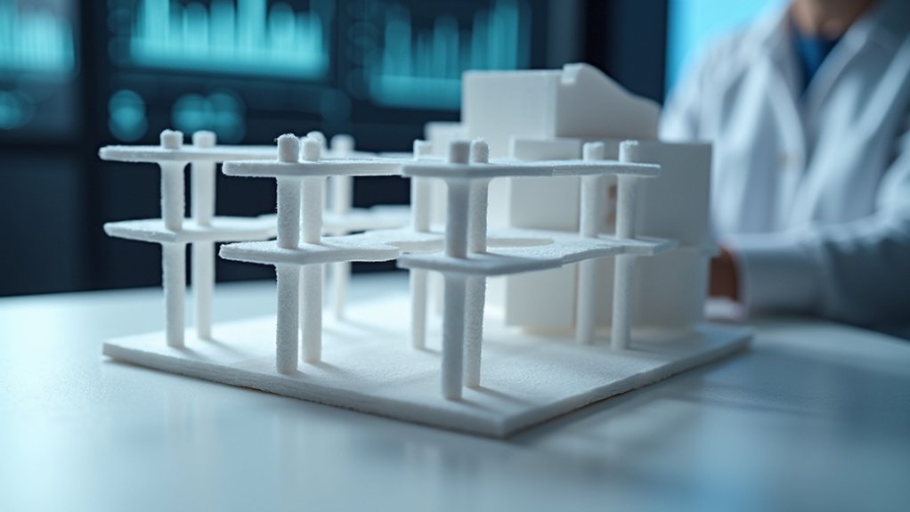
Precision determines the success of your 3D printed structural engineering model. Scaling accuracy is crucial since even minor discrepancies in your digital model can create significant dimensional errors in the final structure.
You’ll need to maintain consistent scale ratios throughout your design process to guarantee all components fit together properly during assembly.
Consider these critical factors for dimensional accuracy:
- Use your software’s scaling features to adjust model size while preserving proportions
- Account for your printer’s resolution and layer height when designing fine details
- Conduct verification checks against original CAD drawings before printing
- Establish clear tolerance requirements for your specific structural application
Your printer’s capabilities directly impact detail fidelity and overall dimensions, making careful consideration of these parameters necessary for successful model creation.
Support Structure Design and Print Parameter Configuration
When you’re designing support structures for your structural engineering models, you’ll need to carefully select materials that balance ease of removal with adequate strength during printing.
Your success depends on understanding overhang angles and bridge spans that require support, as these elements directly affect your model’s accuracy and surface finish.
You’ll also want to optimize layer height settings to guarantee your supports bond properly with the main structure while maintaining the dimensional precision essential for engineering applications.
Support Material Selection Criteria
Although support materials might seem like a secondary consideration, they’ll fundamentally determine your model’s quality and post-processing requirements. Your selection impacts adhesion, surface finish, and the overall integrity of complex designs.
When choosing support materials for structural engineering models, you’ll need to evaluate:
- Material compatibility – Confirm your support material won’t adversely affect the primary material’s adhesion or create unwanted chemical reactions.
- Removal complexity – Consider whether manual removal is feasible for your geometry or if soluble supports are necessary.
- Cost efficiency – Balance material costs against time savings, especially for intricate internal structures.
- Surface finish requirements – Select materials that minimize scarring and post-processing work on critical surfaces.
Strategic material selection streamlines your workflow while preserving model accuracy.
Overhang and Bridge Requirements
Beyond material compatibility lies the fundamental challenge of designing support structures that accommodate overhangs and bridging elements in your structural engineering models.
You’ll need to carefully analyze where overhangs occur and determine ideal support placement to prevent sagging during printing. Bridge structures require strategic load distribution across supports to maintain structural integrity throughout the process.
Configure your print parameters by adjusting layer height, infill density, and support settings to strengthen overhanging sections.
You should utilize simulation software to conduct stress tests and identify potential weaknesses before printing begins. This proactive approach helps you enhance designs for better mechanical properties.
Consider your material choice carefully—high-strength polymers and specialized concrete offer enhanced capabilities for handling complex overhangs and bridging requirements effectively.
Layer Height Optimization
Three critical variables determine your layer height enhancement success: print quality, structural integrity, and production efficiency.
Your layer height selection directly impacts how your structural engineering model performs in real-world applications. Fine layers at 0.1mm deliver exceptional detail but extend printing processes considerably, while 0.5mm heights accelerate production with reduced surface quality.
Consider these essential factors for layer height enhancement:
- Support compatibility – Larger layers need robust supports to prevent structural collapse
- Print parameter integration – Adjust speed and temperature alongside height for peak strength
- Post-processing reduction – Finer layers minimize sanding and finishing requirements
- Material efficiency – Balance detail needs against material consumption
You’ll achieve superior results by coordinating layer height with your specific structural requirements and project timeline constraints.
Layer-by-Layer Printing Process and Quality Control Measures
When you create structural engineering models through 3D printing, the layer-by-layer deposition process becomes your foundation for achieving precise geometric control and desired mechanical properties. You’ll need to implement robust quality control measures throughout each stage to guarantee structural integrity.
| Quality Control Aspect | Monitoring Focus |
|---|---|
| Temperature Control | Material flow consistency |
| Layer Adhesion | Bond strength between layers |
| Dimensional Accuracy | Adherence to specifications |
| Flow Rate Management | Uniform material deposition |
| Calibration Frequency | Equipment precision maintenance |
Your slicing software converts digital models into optimized printable formats, balancing layer height and print speed. You’ll monitor temperature and flow rates continuously while using sensors to detect adhesion issues. Regular printer calibration ensures consistent material deposition across multiple prints, maintaining design specifications and minimizing structural defects.
Post-Processing Techniques for Enhanced Model Durability
After your 3D printed structural model emerges from the printer, you’ll need to apply targeted post-processing techniques to achieve the durability standards required for engineering applications.
These enhancement methods transform raw prints into robust, professional-grade models.
Essential post-processing techniques for enhanced durability include:
- Surface refinement – Sand and smooth layer lines to improve aesthetic quality and structural integrity
- Chemical strengthening – Apply acetone to ABS prints for stronger layer fusion and increased impact resistance
- Protective coating – Use sealants to prevent moisture ingress and chemical damage, extending model lifespan
- UV curing – Expose resin prints to ultraviolet light for maximum hardness and stability
You’ll also want to evaluate mechanical assembly methods like screws or dowels for multi-part models, ensuring connections withstand handling stress.
Assembly Methods for Large-Scale Multi-Component Models
While printer build volumes impose physical constraints on model size, you can overcome these limitations by designing large-scale structural models as interconnected components that assemble into cohesive systems.
Effective assembly methods require strategic planning during the design phase, incorporating mechanical interlocking joints or preparing surfaces for adhesive bonding. You’ll need to embed alignment features like pins or dowels into your CAD models to guarantee precise component positioning during assembly.
Strategic design planning with mechanical joints and embedded alignment features ensures precise component positioning in large-scale structural model assembly.
The construction industry benefits from prototyping these assembly methods before final production. You should test component fit and structural integrity through smaller test prints, identifying potential alignment issues early.
Post-processing techniques like sanding connection surfaces will improve fit quality and overall structural performance, guaranteeing your assembled model accurately represents real-world engineering scenarios.
Testing and Validation of 3D Printed Structural Prototypes
Building and assembling your multi-component structural models represents only the initial phase of prototype development.
Testing and validation are essential steps that guarantee your 3D printed prototypes meet design specifications and perform reliably under real-world conditions.
You can implement thorough validation through several approaches:
- Mechanical Testing – Conduct tensile and compressive strength assessments to verify material properties match your design requirements
- Non-Destructive Examination – Use ultrasonic and X-ray testing to detect internal flaws without damaging your prototype
- Computational Comparison – Compare physical test results with FEA predictions to confirm design accuracy
- Field Testing – Subject components to actual load scenarios and environmental conditions
This iterative testing process allows you to refine designs, enhance performance, and minimize failure risks before full-scale implementation.
Frequently Asked Questions
How Can I Make My Own Models for 3D Printing?
You’ll start by learning CAD software like Fusion 360 or Blender to design your models. Export files as STL format, then use slicing software to prepare them for your specific 3D printer’s requirements.
How Can 3D Printing Be Used in Engineering?
You can use 3D printing in engineering to rapidly prototype components, create complex geometries impossible with traditional manufacturing, customize parts for specific needs, and construct entire structures while reducing costs.
How to Turn an Image Into a 3D Model for Printing?
You’ll convert your image to high-contrast black and white using Photoshop, then import it into Blender. Use “Image to Mesh” tools to extrude the design, check for errors, and export as STL format.
What Software Is Used to Create 3D Models for Printing?
You’ll use CAD software like AutoCAD, SolidWorks, or Fusion 360 to create 3D models. Then you’ll need slicing software like Cura or PrusaSlicer to convert your designs into printable files.



Leave a Reply